Description
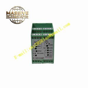
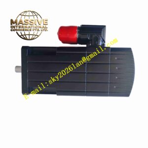
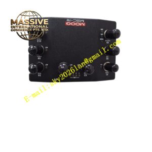
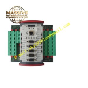
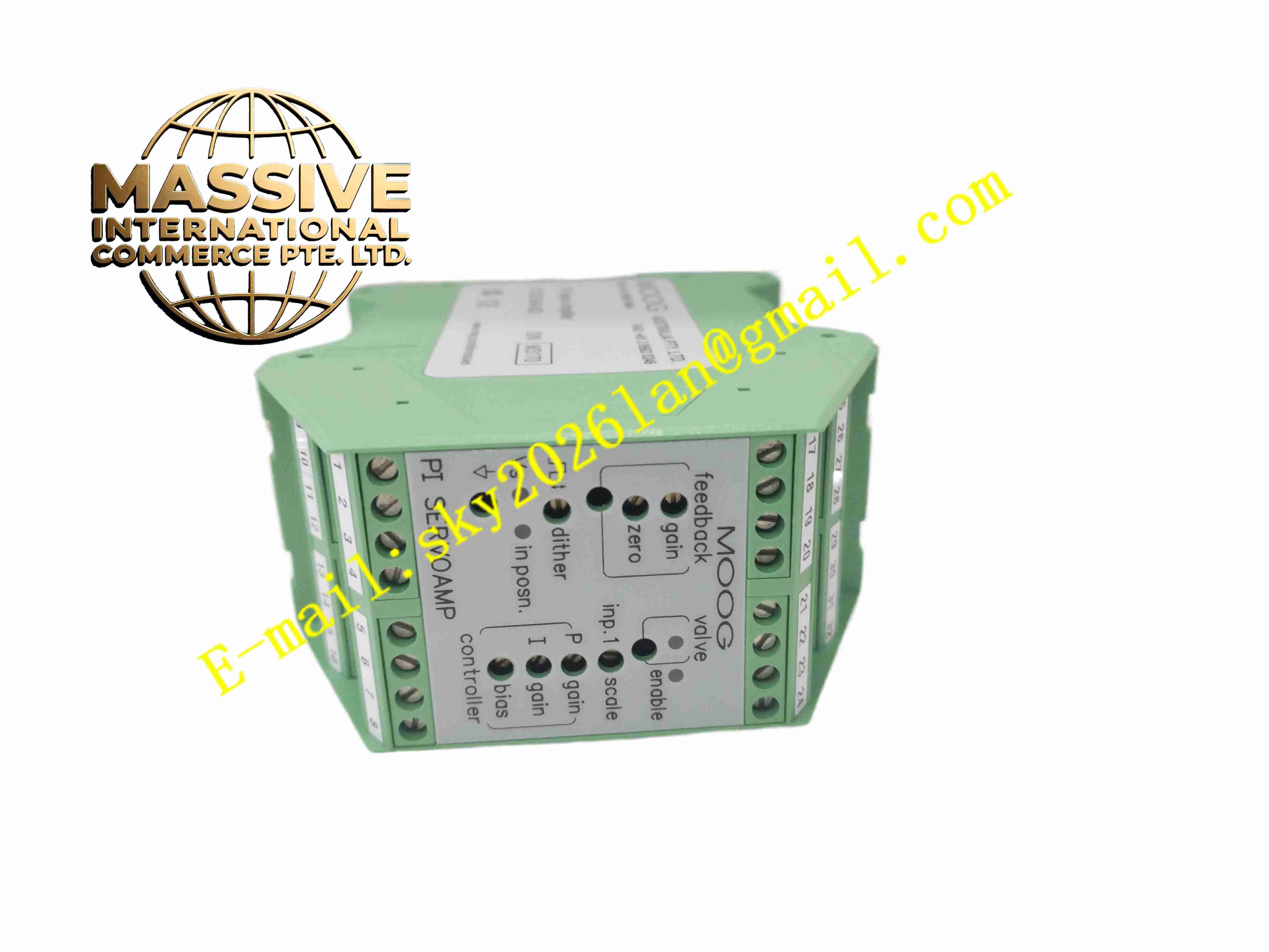
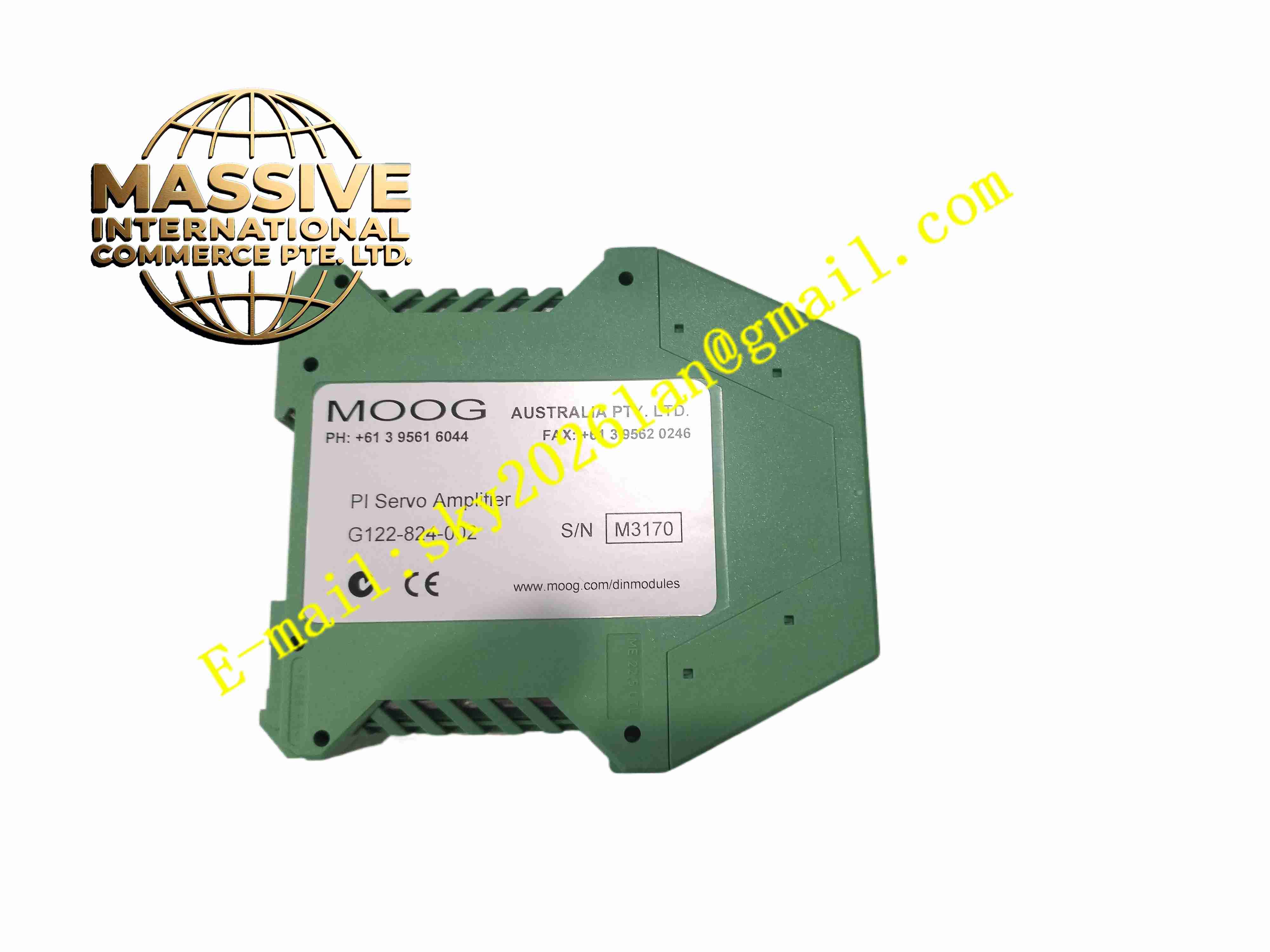
MOOG G122-824-002
Technical Specifications:
- Mounting: Standard 35 mm DIN rail
- Control Algorithm: Proportional / Integral, selectable via internal switches
- Input Signal Types: Differential voltage, single-ended voltage, 4–20 mA current
- Output: Current output for servo valve dual coils
- Frequency Response: 50 kHz maximum switching frequency
- Power Supply: 24 VDC
- Adjustment: Zero and span trim potentiometers on PCB
- Operating Temperature: -20 °C to +60 °C
- Storage Temperature: -40 °C to +85 °C
- Enclosure: Plastic DIN rail housing
- Certification: CE marked
Function Features:
- P-I closed-loop control for proportional and servo hydraulic valves
- Selectable proportional only, integral only or combined P-I control mode via internal DIP switches
- Support 4–20 mA analog input for process control command signal
- Built-in dead band compensation for valve hysteresis correction
- Enable input for system safety interlock and amplifier enable/disable
- Output step test button for on-site valve commissioning
- Internal trim potentiometers for zero offset and span calibration
- Short circuit protection for valve coil output
- Compact DIN rail design for control cabinet installation
Application Scenarios:
- Hydraulic press closed-loop position and force control
- Material testing machine servo hydraulic control
- Steel mill rolling mill hydraulic valve control
- Injection molding machine hydraulic proportional valve drive
- Aerospace component test bench hydraulic servo systems
Material Composition:
- Housing: Flame retardant plastic DIN rail enclosure
- Main PCB: FR4 fiberglass printed circuit board
- Core Components: Analog operational amplifiers, power output MOSFETs, DIP switches
- Terminals: Screw copper terminal blocks for power, input and valve coil wiring
- Passive Components: Precision metal film resistors, low drift capacitors
- Adjustment Components: Multi-turn trim potentiometers
Structural Features:
- Compact rectangular DIN rail snap-on housing
- Side screw terminal blocks for field wiring access
- Internal PCB with DIP switches and trim potentiometers accessible after removing housing cover
- Internal heat dissipation path for power output circuits
- DIN rail clip integrated on rear side of housing
Working Principle: Command signal from PLC or controller and feedback signal from position sensor feed into amplifier input terminals. The circuit calculates error value between command and feedback. P-I algorithm processes error signal, applies proportional gain and integral action. The amplifier outputs regulated current to servo valve dual coils to adjust valve spool position. DIP switches select control mode and dead band compensation value. Trim potentiometers adjust zero offset and full scale gain to match valve characteristics. Enable input cuts off valve drive current when safety interlock opens.
Installation Requirements:
- Mount amplifier on 35 mm DIN rail inside ventilated control cabinet
- Use shielded twisted pair cables for command and feedback signal wiring
- Separate low level control signal cables from high power hydraulic motor cables
- Connect 24 VDC power supply and protective earth
- Keep clearance for heat dissipation around the amplifier
- Avoid installation location with heavy vibration and oil mist
Usage Notes:
- Set DIP switches and perform zero/span calibration before commissioning hydraulic system
- Verify valve coil impedance matches amplifier output rating
- Use enable interlock circuit for emergency stop function
- Disconnect power before opening housing cover to adjust potentiometers
- Do not exceed maximum output current rating for servo valve coils
- Inspect terminal screw tightness periodically under vibration environment