Description
NI 9853
Technical Specifications: Channel count: Two independent CAN FD channels Supported protocol: CAN 2.0A, CAN 2.0B, CAN FD Maximum baud rate: 8 Mbit/s for CAN FD data phase Connector type: D-SUB 9 pin male connector Backplane interface: C Series bus for cDAQ / cRIO chassis Operating temperature range: -40℃ ~ +70℃ Storage temperature range: -40℃ ~ +85℃ Relative humidity: 5% to 95%, non-condensing Form factor: C Series compact module Protection grade: IP20 inside control chassis
Functional Features: Two independent CAN FD channels for simultaneous multi-bus monitoring and simulation. Hardware timestamping for every received and transmitted CAN message. Real-time CAN bus load calculation and monitoring. Detect and record CAN bus error frames, bit errors, stuff errors and CRC errors. Support CAN FD long frame transmission up to 64 bytes payload. Transmit CAN frame data to host controller via C Series backplane bus. Compatible with NI-XNET driver software for bus simulation and diagnostic testing. Built-in bus termination resistor configurable via software command.
Application Scenarios: Automotive ECU hardware-in-the-loop simulation, vehicle CAN bus data logging, heavy duty construction machinery network test, new energy vehicle battery management system testing, industrial mobile machinery control network, railway auxiliary CAN bus monitoring, off-highway vehicle controller validation test.
Performance Parameters: High speed CAN FD frame transmission and reception with hardware timestamp. Real-time capture of all bus error events for bus fault analysis. High channel bandwidth for high bus load continuous data recording. Continuous operation: 24 hours stable CAN bus communication in test cabinet environment. High noise immunity for vehicle and mobile machinery harsh electromagnetic environment.
Material Composition: PCB substrate: Multi-layer FR4 glass fiber epoxy printed circuit board. Core components: CAN FD protocol controller, CAN transceiver, hardware timestamp logic chip, ESD protection array. Housing: Black flame retardant PA plastic enclosure. Front connector: 9 pin D-SUB metal shell connector with gold plated pins. Internal passive components: High grade industrial resistors and capacitors for bus termination and ESD protection.
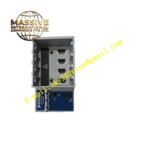
Structural Features: Compact C Series module form factor for cDAQ and cRIO chassis slot installation. Front panel with dual 9 pin D-SUB CAN bus connectors and communication status LEDs. Internal circuit layout separated into CAN transceiver area, protocol processing area and backplane communication area. C Series gold edge connector at module rear for power supply and digital bus communication. Isolation circuit between CAN field bus and chassis backplane circuit.
Working Principle: NI 9853 receives power supply from cDAQ or cRIO chassis backplane. CAN bus signal from external network enters module through D-SUB connector. CAN transceiver converts differential CAN bus signal into single-ended digital signal for protocol controller. CAN FD controller performs frame parsing, CRC check and hardware timestamp for received messages. Messages from host controller are packaged into CAN frames and transmitted onto CAN bus through transceiver. Module continuously monitors bus status and captures all error frames, then transmits frame data and diagnostic information to host controller via C Series backplane bus.
Installation Requirements: Power off chassis before inserting or removing NI 9853 module. Insert module into empty C Series slot and lock retaining latch. Connect CAN bus shielded twisted pair cable to D-SUB connectors. Configure bus baud rate, termination resistor and CAN protocol mode in NI-XNET software. Install bus termination resistor at physical ends of CAN network. Ensure chassis protective earth ground connection is reliable. Separate CAN signal cables from high power cables to reduce interference.
Usage Notes: Hot swap operation is forbidden when chassis is energized. Use certified CAN shielded twisted pair cable for field bus wiring. Set correct bus termination resistor to avoid signal reflection. Backup XNET project configuration before modifying bus parameters. Wear anti-static wristband when handling module. Regularly inspect D-SUB connector tightness during maintenance. Do not apply voltage exceeding transceiver rated range to CAN bus terminals.