Description
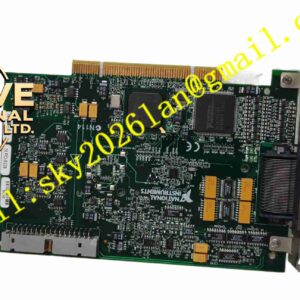
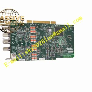
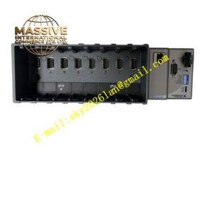
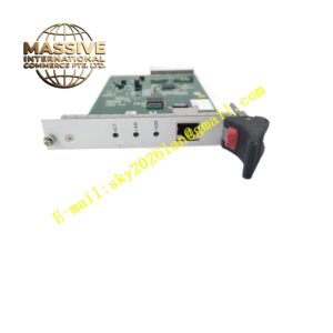
NI 9205
Technical Specifications: Channel configuration: 32 single-ended / 16 differential analog voltage input ADC resolution: 16 bit Maximum sampling rate: 250 kS/s aggregate sampling rate Programmable input ranges: ±10 V, ±5 V, ±1 V, ±0.2 V Input isolation: Channel-to-earth overvoltage protection Connector options: 36-position spring terminal, 37-pin D-SUB Operating temperature range: -40℃ ~ +70℃ Storage temperature range: -40℃ ~ +85℃ Relative humidity: 5% to 95%, non-condensing Form factor: C Series compact module for cDAQ / cRIO chassis Protection grade: IP20 when installed in chassis
Functional Features: Multi-channel analog voltage signal acquisition for industrial sensors and test points. Programmable per-channel gain to match different sensor output voltage ranges. 16-bit high resolution analog to digital conversion for precise voltage measurement. Built-in overvoltage protection to protect circuit from wiring error and transient voltage surge. Support both single-ended and differential wiring to reduce common mode noise interference. Transmit digital measurement data to cDAQ or cRIO controller via C Series backplane bus. Compatible with LabVIEW programming environment for data logging and analysis. On-board circuit self-test function for hardware fault diagnosis.
Application Scenarios: Industrial machine condition monitoring, product validation test bench, battery pack voltage measurement, hydraulic and pneumatic system pressure transducer acquisition, laboratory multi-channel data logging, vibration sensor voltage signal collection, automotive component durability testing, aerospace component ground test system.
Performance Parameters: Guaranteed no missing codes across full ADC measurement range. High multiplexing speed for sequential multi-channel sampling. High common mode noise rejection under differential wiring configuration. Continuous operation: 24 hours stable data acquisition inside industrial test cabinet. Fast data transfer through C Series backplane to host controller.
Material Composition: PCB substrate: Multi-layer FR4 high reliability glass fiber epoxy printed circuit board. Core components: 16-bit ADC chip, programmable gain instrumentation amplifier, signal multiplexer, backplane communication controller. Module housing: Black flame retardant PA plastic enclosure. Connectors: Gold plated copper alloy contact pins, PA66 flame retardant plastic connector housing. Spring terminal version uses push-in spring metal contacts for fast wiring.
Structural Features: Compact rectangular C Series module structure for direct insertion into cDAQ / cRIO chassis slot. Front panel equipped with signal connector and printed channel pin assignment diagram. Internal circuit divided into analog signal input area, multiplexer and amplifier area, ADC conversion and digital communication area. Back side C Series gold edge connector for power supply and digital bus communication with chassis backplane. Internal metal shielding layer to suppress electromagnetic interference between analog and digital circuits.
Working Principle: After inserting into cDAQ or cRIO chassis, the module receives power supply from chassis backplane. Analog voltage signals from external sensors enter the module through front connector. Signal multiplexer sequentially selects each input channel, then signal passes to programmable gain amplifier to adjust signal amplitude to match ADC input range. ADC converts conditioned analog voltage signal into 16-bit digital value. Digital data is transmitted to chassis controller through C Series backplane bus. Overvoltage protection circuit continuously monitors input signal and clamps abnormal high voltage to protect internal circuit.
Installation Requirements: Power off cDAQ or cRIO chassis before inserting or removing NI 9205 module. Insert module into empty C Series slot and lock module retaining latch. Wire sensor cables to spring terminal or D-SUB connector according to wiring diagram. Configure channel input range and channel mode in NI measurement software. Ensure chassis protective earth ground connection is reliable. Reserve ventilation clearance around chassis for heat dissipation. Separate analog sensor signal cables from high power cables in different cable trays.
Usage Notes: Hot swap operation is forbidden when chassis backplane is energized. Do not apply voltage exceeding rated maximum input range to input channels. Use shielded twisted pair cable for long distance analog signal wiring. Wear anti-static wristband when handling module. Regularly inspect connector wiring tightness during maintenance. Do not expose module to environment beyond rated temperature and humidity range. Prevent liquid and conductive dust from entering connector area.