Description
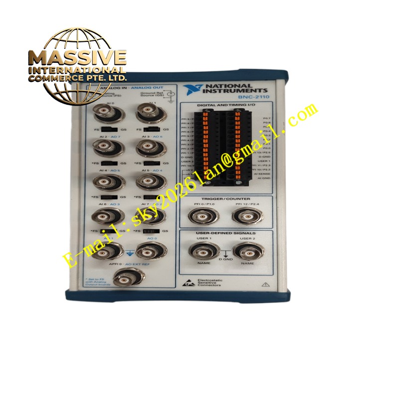
NI BNC-2110
Technical Specifications Compatible with NI M Series DAQ devices; 16 analog input BNC connectors, 2 analog output BNC connectors, digital I/O screw terminals; 1000V CAT I isolation rating; 20-pin ribbon cable interface to DAQ device; operating temperature 0°C to +55°C; metal shielded enclosure; BNC 50-ohm coaxial interface standard.
Functional Features Route analog input and analog output signals between DAQ hardware and coaxial measurement probes via BNC connectors. Provide accessible screw terminals for digital trigger and digital I/O signals. The metal housing provides electromagnetic shielding to reduce noise interference on low-level analog signals. Support signal routing for single-ended and differential analog measurement configurations. Simplify test wiring by standard coaxial connection for signal generators and oscilloscope probes.
Application Scenarios Laboratory signal acquisition, sensor dynamic signal testing, educational measurement experiment systems, automated product test benches, low-frequency analog signal recording.
Performance Parameters Controlled signal impedance matching; high shielding effectiveness against external electromagnetic interference; low crosstalk between adjacent analog channels; stable BNC connector mechanical contact performance.
Material Composition Enclosure is painted steel sheet metal for electromagnetic shielding; BNC connectors have gold-plated center pins and nickel-plated shells; internal signal wiring uses shielded coaxial wire; terminal block contact springs are nickel-plated copper alloy; internal PCB substrate is FR-4 flame-retardant board.
Structural Characteristics Rectangular desktop metal enclosure. Front panel populated with BNC coaxial connectors for analog signals. Rear panel includes a 20-pin ribbon cable port and screw terminal blocks for digital signals. Internal shielding partitions separate analog signal channels to reduce crosstalk. Rubber foot pads support desktop placement.
Working Principle Analog signals carried by coaxial cables connect to BNC front panel connectors and route through internal shielded traces to the ribbon cable port. The ribbon cable transmits signals to the connected NI DAQ acquisition card. Digital signals connect via rear screw terminals and route through internal traces to the same ribbon interface. The continuous metal shield of the enclosure and BNC shells suppress external electromagnetic noise coupling into measurement circuits.
Installation Requirements Place the terminal block on a stable desktop or equipment rack shelf. Connect the supplied ribbon cable between BNC-2110 and the compatible NI DAQ device. Attach coaxial test cables to front-panel BNC ports. Wire digital trigger and digital I/O signals to rear screw terminals. Verify shielding ground connection before starting measurement tasks.
Precautions for Use Do not apply voltage exceeding rated CAT I voltage limit to BNC input ports. Use properly terminated 50-ohm coaxial cables for high-frequency signals. Keep the unit away from large transformers and motor drive equipment. Disconnect DAQ device power before modifying ribbon cable connections.