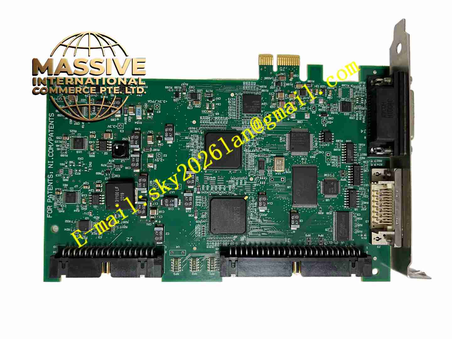
Description
NI PCIE-1427
Technical Specifications: Bus interface: PCI Express 1.1 Camera interface: Camera Link Base configuration, single camera port Pixel clock frequency range: 20 MHz to 85 MHz Pixel depth support: 8 bit, 10 bit, 12 bit, 16 bit Digital I/O: 2 optically isolated digital input channels,4 TTL digital input channels Encoder input:1 quadrature RS-422 encoder input channel Trigger function: Hardware trigger input for synchronized frame capture Power supply: Powered by PCIe slot of host PC Operating temperature range:0℃ ~ +55℃ Storage temperature range:-40℃ ~ +85℃ Relative humidity:5% to 90%, non-condensing Connector: Camera Link MDR26 connector and D-SUB connector for digital signals Form factor: Full-height PCIe add-on card Protection grade:IP20
Functional Features: Support Camera Link Base industrial camera for high-speed digital image transmission. Hardware region of interest function reduces data volume by capturing only target image area. Onboard image binarization preprocessing reduces image processing load on host PC. Optically isolated digital input channels receive external trigger signals from sensors and photoelectric switches. Quadrature encoder input realizes position-synchronized image capture for moving web or conveyor objects. Compatible with NI Vision Acquisition Software and LabVIEW vision development tools. Hardware trigger mode starts frame acquisition upon external signal edge detection. Onboard image buffer temporarily stores frame data to prevent frame loss during high-speed acquisition. Power-on self-test verifies camera communication and onboard hardware integrity.
Application Scenarios: Electronic component surface defect inspection, printed product barcode and text reading, part dimension measurement, packaging quality inspection, semiconductor component visual inspection, scientific microscopic imaging, automotive part surface visual detection.
Performance Parameters: Stable high-speed pixel data transmission within 85MHz maximum pixel clock limit. Accurate frame synchronization with encoder position signal for continuous moving object imaging. Isolated trigger input eliminates industrial noise interference for trigger signal. Continuous frame streaming without frame drop under host memory sufficient condition. Reliable long-time continuous image acquisition in industrial cabinet environment.
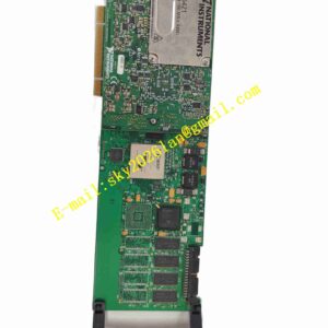
Material Composition: PCB substrate: Multi-layer FR4 high TG glass fiber epoxy printed circuit board. Core components: Image receiving FPGA, PCIe interface controller, Camera Link LVDS receiver chip, optocoupler isolation array, high-speed image buffer memory. Mechanical bracket: Steel full-height PCIe mounting bracket. Connectors: Metal shielded MDR26 Camera Link connector and metal D-SUB connector for digital I/O.
Structural Features: Standard full-height PCIe add-on card layout for industrial PC PCIe slot installation. Steel rear bracket fitted with MDR26 Camera Link port and D-SUB digital signal port. Internal circuit divided into PCIe host bus interface zone, Camera Link high-speed signal receiving zone, isolated digital I/O zone and FPGA logic zone. Differential signal routing for LVDS Camera Link signals to maintain signal integrity at high pixel clock frequency. Gold-plated PCIe edge connector for PCIe bus connection.
Working Principle: PCIe-1427 receives power supply from PCIe slot after installation into host PC. Vision driver initializes FPGA and communication hardware. Industrial Camera Link camera transmits pixel data, clock and control signals through MDR26 cable to frame grabber. LVDS receiving circuit converts differential camera signals into digital pixel data, FPGA receives pixel stream and stores image frames into onboard buffer. Image data is transmitted to host PC memory through PCIe bus. External trigger sensor or quadrature encoder signal is fed into isolated digital input channel, FPGA captures trigger edge and controls frame capture timing. Hardware ROI module extracts target image region before sending image data to PC. Vision software completes image analysis and measurement on host computer.
Installation Requirements: Power off host industrial PC before installing PCIe-1427 frame grabber. Insert card into empty PCIe slot and fasten steel bracket screw. Install NI Vision Acquisition Software and LabVIEW vision module on host operating system. Connect Camera Link MDR26 shielded cable between frame grabber and industrial camera. Connect trigger sensor and quadrature encoder wiring to D-SUB connector. Launch NI configuration tool, run hardware self-test and camera communication verification. Set pixel clock, trigger mode and ROI parameters inside vision project. Ground PC chassis reliably to reduce electromagnetic interference for Camera Link signal. Use high-quality shielded Camera Link cable and keep cable length within rated maximum limit.
Usage Notes: Use dedicated shielded MDR26 Camera Link cable to avoid high-speed signal distortion. Wear anti-static wristband during card installation and camera wiring work. Backup vision inspection project before modifying acquisition parameters. Do not exceed maximum 85MHz pixel clock rating of the board. Prevent bending and pulling force on Camera Link cable during equipment operation. Do not operate card outside rated temperature and humidity range. Prevent dust accumulation on connector pins.