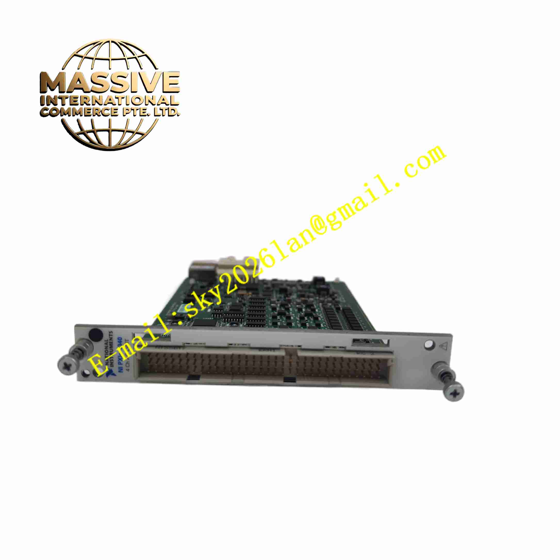
Description
NI PXIe-4340 Analog Input Module
Technical Specifications Model: PXIe-4340 Form Factor: 3U single slot PXI Express module Number of Input Channels: 8 differential analog input channels ADC Resolution: 24-bit Input Type: Differential voltage input, suitable for Wheatstone bridge sensors Built-in Excitation: Programmable excitation voltage for bridge sensors Isolation Voltage: Channel-to-chassis isolation Operating Temperature: 0 ℃ ~ +55 ℃ Storage Temperature: -40 ℃ ~ +70 ℃ Relative Humidity: 10% ~ 70% non-condensing Front Connector: 37-pin D-SUB connector Mounting: PXI Express chassis slot installation
Functional Features 24-bit high resolution ADC provides high precision low-level signal acquisition for strain sensors. Built-in programmable excitation source supplies power for quarter-bridge, half-bridge and full-bridge strain gauge. Built-in bridge completion resistors for quarter-bridge sensor configuration. Programmable digital filter suppresses 50 Hz and 60 Hz power line noise. Channel to chassis electrical isolation protects PXI system from common-mode voltage. Supports TEDS sensor automatic identification and parameter reading. PXI trigger bus synchronization supports multi-module synchronized sampling. Compatible with NI-DAQmx driver for programming and configuration.
Application Scenarios Mechanical stress and strain measurement, structural fatigue test, load cell force measurement, pressure sensor data acquisition, vibration test, aerospace component structural test, automotive crash test data collection.
Performance Parameters High signal resolution for microvolt-level strain signal measurement. Isolation circuit withstands specified common-mode voltage without measurement distortion. Digital filter effectively eliminates power frequency interference in industrial environment. Sampling time can be configured to balance sampling speed and noise suppression. Module maintains stable acquisition performance under continuous vibration test environment. TEDS function reads sensor calibration parameters automatically without manual entry.
Material Composition Module Housing: Flame-retardant plastic front panel and metal shielding frame. Main PCB: FR4 multi-layer industrial printed circuit board with conformal coating. Core Electronic Components: 24-bit ADC chip, precision reference voltage chip, bridge completion resistors, isolation components, FPGA, flash memory, static protection diodes. Connector: Gold-plated 37-pin D-SUB front connector and gold-plated PXIe backplane edge connector. Indicator Components: LED power and fault indicators on front panel. Fasteners: Stainless steel screws and metal fixing clips.
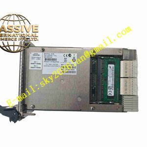
Structural Features 3U single-slot standard PXIe module mechanical dimension. Front panel equipped with 37-pin D-SUB signal connector and LED indicators. Metal shielding shell reduces electromagnetic interference. Rear gold-plated edge connector mates with PXIe chassis backplane for power and bus communication. Internal isolation barrier separates field analog signal circuit and digital PXI bus circuit. Reserved ventilation gaps for chassis forced cooling airflow.
Working Principle The module obtains DC power and PXIe bus communication signal from PXIe chassis backplane. Built-in programmable excitation source outputs stable excitation voltage to Wheatstone bridge sensors connected to front D-SUB connector. When mechanical deformation occurs on strain gauge, bridge circuit generates tiny differential voltage signal. The signal enters module differential input channel, then passes through signal conditioning circuit and digital filter. 24-bit ADC converts analog differential signal to digital value. Onboard FPGA receives digital sampling data and transmits to host controller through PXIe bus. TEDS circuit reads sensor stored calibration information automatically. Isolation circuit blocks high common-mode voltage from field side to protect PXI chassis hardware.
Installation Requirements Power off PXIe chassis before inserting or removing module. Align module with empty PXIe slot, push steadily until backplane connector fully engages and front panel locks. Connect strain gauge or bridge transducer to front 37-pin D-SUB connector according to pin definition. Install NI-DAQmx driver and NI MAX configuration software on host computer. Power on chassis, complete hardware recognition and sensor parameter configuration. Set excitation voltage, filter parameters and sampling rate in configuration software. Reserve cooling airflow space around module slot.
Usage Precautions Do not apply voltage exceeding channel isolation rating to input terminals. Use shielded twisted pair cable for strain sensor wiring, single-point grounding of shield. Avoid strong vibration and impact on module during operation. Prevent condensation and conductive dust inside PXI chassis. Do not disassemble module housing without professional authorization. Check wiring integrity and terminal tightness regularly in long-term test system. Calibrate module periodically according to manufacturer specification.