Description
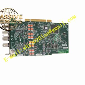
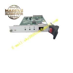
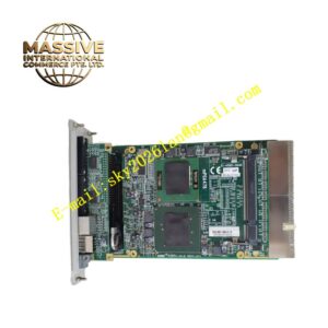
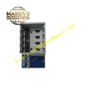
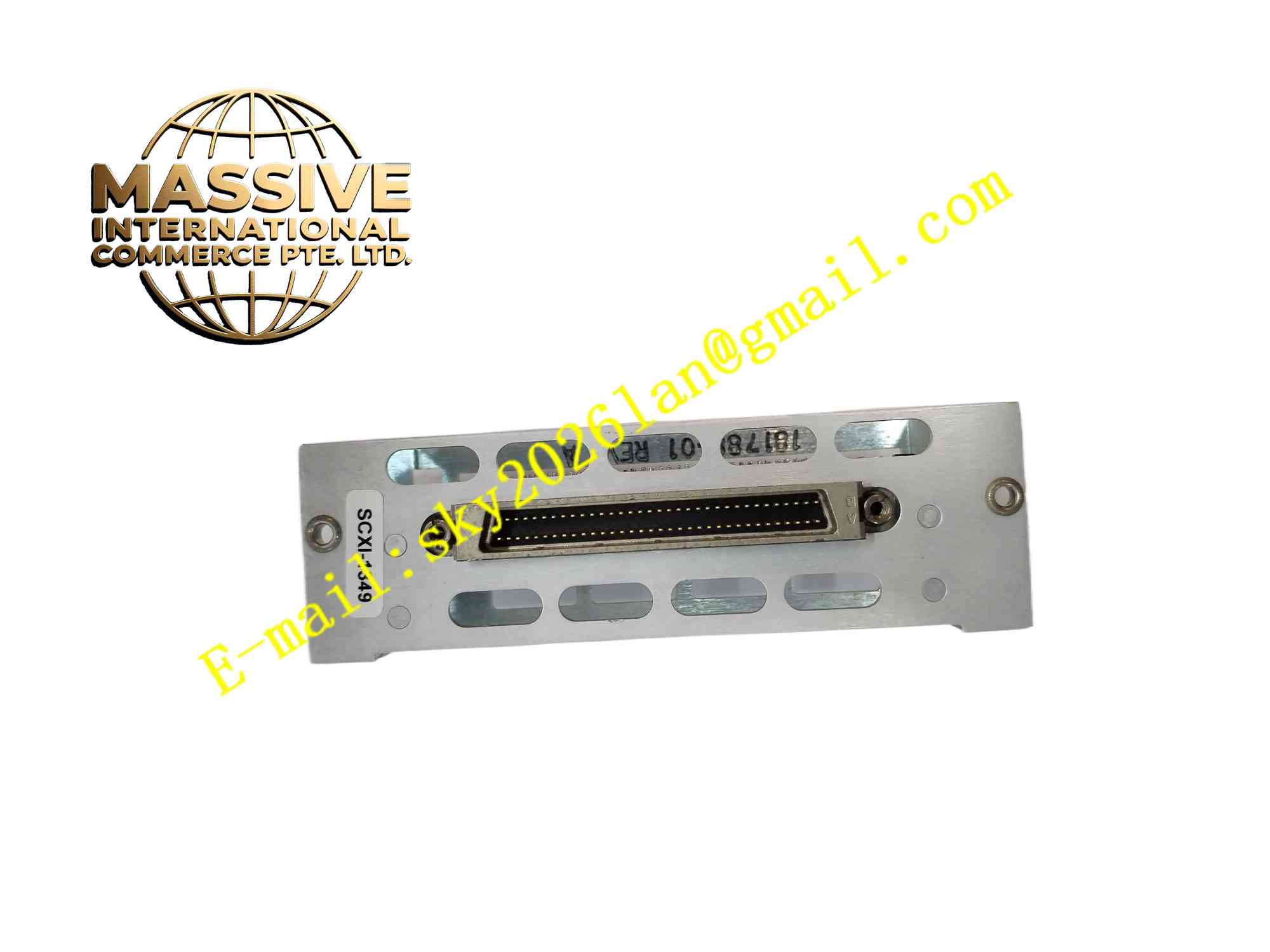
NI SCXI-1349
Technical Specifications Brand: NI (National Instruments) Model: SCXI-1349 Compatible Modules: SCXI-1125, SCXI-1126 and other matched SCXI high-voltage analog input modules Terminal Type: Screw-clamp terminal block Number of Channels: 32 differential signal channels Max Common-Mode Voltage: ±300 V Wire Gauge Range: 14 AWG to 26 AWG Operating Temperature: 0°C to +50°C Humidity: 10% to 90% non-condensing Protection Grade: IP20 for cabinet mounting Connection Interface: Ribbon cable interface to SCXI front module connector
Functional Features 32 differential wiring terminals for multi-channel analog signal access. Built-in transient voltage suppression components protect measurement circuits against voltage surges. Screw-clamp terminals enable stable fastening of discrete sensor wires without soldering. Labeled channel marking on terminal block simplifies wiring inspection and maintenance. Ribbon cable connection realizes fast mechanical coupling between terminal block and SCXI module. Supports high common-mode voltage measurement for industrial field signal collection. Modular design allows quick removal and replacement without reworking field wiring.
Application Scenarios High voltage industrial sensor data acquisition, power equipment voltage monitoring, multi-channel test bench measurement system, machine condition monitoring, power electronics automated test stations.
Performance Parameters Low contact resistance at screw terminals for stable signal transmission. Transient suppression circuit absorbs fast voltage spikes from industrial environment. Consistent channel impedance across all input terminals. Maintain reliable electrical connection under mechanical vibration in industrial cabinets. Low signal attenuation for low-level analog measurement signals.
Material Composition Terminal Housing: Flame-retardant black thermoplastic. Conductive Terminal Inserts: Tin-plated copper alloy. Screws: Zinc-plated carbon steel. Surge Protection Devices: Solid-state TVS semiconductor components. Ribbon Cable Connector: Gold-plated copper contact pins with plastic shell.
Structural Features Rectangular flat plastic housing with channel number printed on front surface. Two rows of screw terminals arranged orderly for 32 differential channels. Rear edge mounted ribbon cable socket connects to SCXI module. Internal PCB traces route each terminal channel independently without crosstalk interference. Mounting holes on housing for fixing to cabinet panel or module bracket.
Working Principle Field sensor wires are fastened to screw terminals. Analog signals pass through internal protection components and PCB traces, then transmit via ribbon cable to matched SCXI analog input module. The transient suppression components clamp excessive voltage spikes before signals enter measurement module. Differential wiring structure rejects common-mode noise on field signal cables.
Installation Requirements Power off SCXI chassis and matched module before installation. Secure terminal block to mounting bracket or cabinet panel. Strip wire insulation to specified length and tighten terminal screws with proper torque. Connect ribbon cable between SCXI module and SCXI-1349 terminal block. Route signal cables separately from high-power AC wiring to reduce electromagnetic interference. Verify wire connection channel by channel after wiring completion.
Usage Notes Do not apply voltage exceeding ±300 V common-mode rating to terminals. Check screw tightness periodically in vibration intensive equipment cabinets. Use shielded twisted-pair cables for analog sensor wiring. Prevent conductive dust and metal debris accumulation on terminal surface. Disconnect all field wiring before removing terminal block.