Description
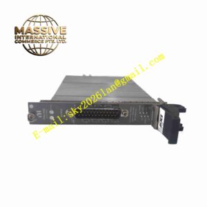
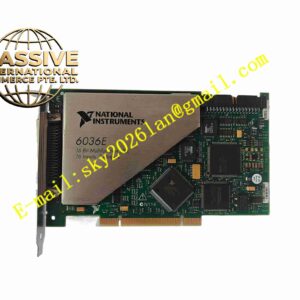
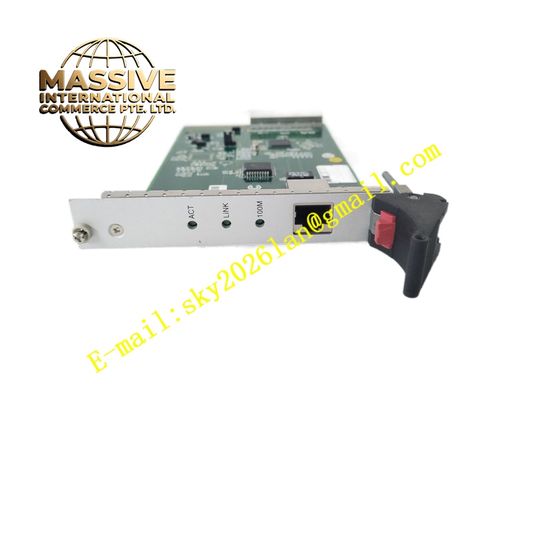
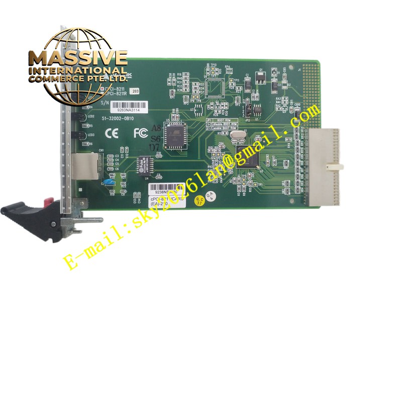
NI CPCI-8211
Technical Specifications Module capacity: 16 isolator modules; safe area connection: screw-clamp terminals rated for 2.5 mm² conductor; bus power input range 21 VDC to 35 VDC; weight of bare backplane 419 g; dimensions 285 mm depth × 175 mm height; mounting options include DIN rail via DMK01 kit, surface mount via SMS01 kit; compatible accessories include earth rail kit ERK16, tagging strip TSK16 and spare fuse packs.
Functional Features Distributes common bus power to all plugged MTL5000 isolators; consolidated safe-area signal terminals reduce scattered field wiring; mechanical retention holds each isolator module securely; optional earth rail provides equipotential bonding for intrinsic safety installation; spare fuse locations protect bus power for each channel.
Application Scenarios Oil refinery hazardous area signal isolation, chemical plant 4-20 mA transmitter barrier racks, natural gas pipeline instrumentation cabinets, pharmaceutical explosion-risk zone signal conditioning and petrochemical DCS I/O marshalling cabinets.
Material Composition Flame-retardant glass fiber PCB substrate; copper power and signal traces with tin plating; reinforced plastic terminal housing; metal mounting lugs; screw-clamp terminal hardware with anti-loosening spring washers.
Structural Characteristics Flat rack backplane PCB; front side module slots for MTL5000 isolator plug-in; safe-area screw terminals arranged along one edge; dedicated mounting holes for DIN rail or surface plate; bus power fuse positions accessible from front side.
Working Principle DC power supply feeds the backplane bus. Each inserted MTL isolator receives bus power and connects field hazardous-area signals through internal barrier circuits. Safe-side DCS wiring terminates on the screw-clamp terminals of this backplane, forming galvanically isolated signal path between hazardous zone and control room.
Installation Requirements Mount backplane inside non-hazardous control cabinet; use specified DIN rail mounting kit; connect earth rail to cabinet protective earth bar; torque terminal screws to manufacturer specified value; install correct fuse rating for bus power.
Operation Notes Do not plug or remove isolator modules while hazardous field circuit remains energized; verify intrinsic safety certification match between isolator, backplane and field apparatus; inspect terminal tightness after cabinet transportation or seismic event.