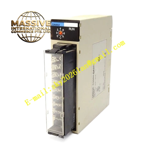
Description
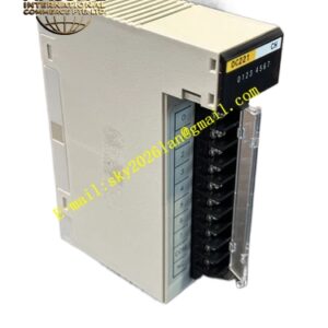
OMRON C200H-ID217
Technical Specifications:
- Brand: OMRON
- Model: C200H-ID217
- Product Type: Digital Input Unit
- Compatible System: C200H Series PLC
- Input Points: 16 points
- Input Voltage: 24 VDC
- Input Type: DC Input (Sink)
- External Connection: Connector type
- Isolation: Photocoupler isolation
Functional Features:
- 16 points of DC 24V digital input
- High-speed response for precise signal detection
- Photocoupler isolation between input circuits and internal logic
- LED indicators for monitoring input status
- Connector-type wiring for simplified installation and maintenance
Application Scenarios:
- Factory automation and production line control
- Machine tool control systems
- Material handling equipment
- Packaging machinery
- Any application requiring reliable digital signal acquisition
Performance Parameters:
- Input Points: 16
- Input Voltage: 24 VDC
- Response Time: High-speed DC input
- Isolation Method: Photocoupler
Material Composition:
- Industrial-grade electronic components
- Multi-layer printed circuit board
- Plastic housing
- Connector terminals
Structural Features: The C200H-ID217 features a compact modular design that mounts directly onto the C200H series backplane. The front panel includes LED indicators for each input point, allowing operators to visually verify signal status at a glance.
Working Principle: The C200H-ID217 receives external DC 24V signals through its input terminals. These signals pass through photocouplers which provide electrical isolation between the field wiring and the internal PLC circuitry. The isolated signals are then processed and made available to the PLC CPU for logic operations.
Installation Requirements:
- Mount on series backplane
- Ensure proper grounding of the system
- Use connector-type wiring for field connections
- Keep signal cables away from high-voltage power lines
- Maintain adequate spacing for ventilation
Usage Notes:
- Verify input voltage polarity before connection
- Do not apply voltages exceeding the rated specifications
- Avoid installation in environments with corrosive gases
- Store spare units in dry, anti-static conditions
- Check connector tightness periodically during maintenance