Description
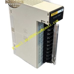
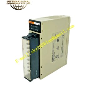
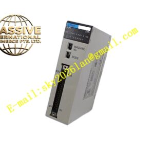
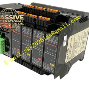
OMRON F350‑CEOV2
Technical Specifications: Power supply DC24V, allowable range DC20.4‑28.8V; power consumption 0.15A maximum; digital input and output PNP type; supports up to 32 connected slave devices; conforms to CE, UL industrial standards; operating temperature 0‑50°C; storage temperature ‑20‑70°C; humidity 10‑90%RH without condensation; DIN‑rail mounting structure; multiple LED status indicators for power, communication and I/O status.
Functional Features: Receives external trigger signals to activate vision image‑capture actions; outputs inspection OK / NG judgment results to external control equipment; provides stable communication interface for vision host and field automation devices; hardware status LED indicators simplify on‑site fault diagnosis; compact DIN‑rail installation saves cabinet space; electrical isolation protects vision main unit from field‑side surge interference.
Application Scenarios: Production‑line visual defect inspection stations; packaging product appearance detection; part dimension visual measurement; barcode and character recognition automation systems; F350 vision system retrofitting and spare‑part replacement.
Performance Parameters: Fast signal response matches high‑speed production‑line tact time; built‑in surge suppression circuit for field‑side signals; continuous long‑term stable operation inside industrial control cabinets; meets industrial electromagnetic compatibility requirements.
Material Composition: Black V0 flame‑retardant plastic housing; internal FR‑4 multilayer PCB; brass nickel‑plated screw terminal blocks; opto‑coupler isolation chips; high‑brightness multi‑color LED indicators; metal DIN‑rail spring buckle.
Structural Features: Compact rectangular DIN‑rail housing; spring‑loaded DIN‑rail buckle on rear face; front‑panel screw terminals for signal and power wiring; multi‑group LED indicators on front panel showing power, communication and channel status; side mechanical locking structure for stacking installation.
Working Principle: External trigger signals pass through opto‑coupler isolation circuit and transmit trigger commands to F350 vision main controller. After vision algorithm completes image analysis, judgment result is transmitted to F350‑CEOV2 internal circuit from vision host, then drives output transistor to switch external signal channels. Module monitors power supply and communication link conditions continuously and reflects abnormal status via LED indicators.
Installation Requirements: Mount on standard cabinet DIN rail; reserve surrounding space for heat dissipation; power and signal wiring use shielded cables; separate signal cables from high‑power inverter and motor cables; cabinet must implement reliable protective grounding.
Usage Notes: Supply voltage must stay within DC20.4‑28.8V; hot‑plugging is forbidden; wiring must be performed under power‑off condition; cannot operate under condensation or corrosive‑gas environment; check terminal screw fastening status regularly.