Description
OMRON CS1W-SCB21-V1
Technical Specifications: Communication interface: 2‑channel RS‑232C, 9‑pin D‑SUB male connectors; supported baud rate range from 1200 bps up to 38400 bps; supported protocols include Host Link, NT Link, Protocol Macro, No‑protocol mode, Modbus‑RTU slave; power supply draws 280 mA from CPU internal DC5V bus; operating temperature 0‑55°C; storage temperature ‑20‑75°C; operating humidity 10‑90%RH without condensation; dielectric withstand voltage 500 VAC for 1 minute between signal circuit and internal logic; weight 100 g; CE and UL certification; no external rack slot occupation; built‑in LED indicators for communication status monitoring
Functional Features: Two independent RS‑232C channels support separate protocol configuration for each port; no consumption of CS‑series rack I/O slots, fully utilizing CPU internal expansion space; protocol macro function executes customized serial data transmission and reception logic; Modbus‑RTU slave function enables seamless connection with Modbus master devices; front‑panel LED indicators display transmit and receive signal status for rapid field fault diagnosis; compatible with full range of CS‑series CPU units; supports interrupt‑driven data reception to improve serial response performance
Application Scenarios: CS‑series PLC connecting to serial human‑machine operation terminals; communication with barcode scanners, serial printers and serial measuring instruments; Modbus‑RTU serial network data interaction; program upload and download through serial channel; legacy CS‑series automation system spare‑part replacement; factory equipment serial data collection and uploading.
Performance Parameters: Conforms to IEC 61000‑6‑4 industrial electromagnetic compatibility standards; signal isolation circuit suppresses common‑mode interference from field serial cables; vibration and shock resistance comply with cabinet‑mount industrial component standards; supports continuous 24‑hour stable operation inside control cabinets.
Material Composition: High‑grade FR‑4 multilayer glass‑fiber printed circuit board; RS‑232C transceiver chips; optocoupler isolation components; metal‑shell 9‑pin D‑SUB male connectors; gold‑plated spring contact pins for CPU internal slot connection; high‑brightness SMD LED status indicators; black flame‑retardant plastic fixing bracket.
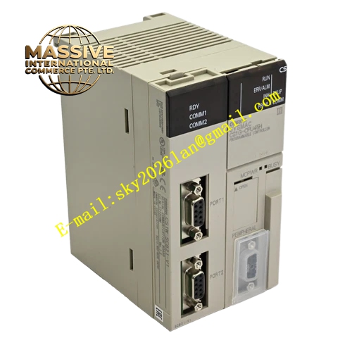
Structural Features: Compact embedded circuit‑board form factor for CPU internal slot installation; gold‑plated spring contact pins on rear side realize electrical connection with CPU internal backplane; two metal‑shell D‑SUB connectors extend to CPU front panel for external serial cable plug‑in; small overall dimension, entirely embedded inside CPU housing without extra cabinet space occupation; mechanical locking structure ensures stable insertion inside CPU slot.
Working Principle: After CS‑series CPU completes power‑on initialization, CS1W‑SCB21‑V1 obtains DC5V working power through CPU internal slot contacts. Internal logic circuit receives sending data from CPU memory area, converts parallel logic data into serial RS‑232C level signals via transceiver chip and optocoupler isolation circuit, and transmits data frames to external serial devices through D‑SUB connectors. Meanwhile, received serial level signals convert into parallel logic data, then transmit to CPU user program area for data processing. Internal hardware circuit monitors communication status in real time and drives LED indicators to reflect transmit‑receive activity.
Installation Requirements: Cut off complete power supply of CS‑series CPU before board installation; insert CS1W‑SCB21‑V1 fully into CPU internal dedicated communication board slot and confirm mechanical locking completion; adopt shielded RS‑232C cables for external wiring; maximum cable length shall not exceed 15 meters; separate serial signal cables from high‑power motor and inverter power cables; guarantee reliable protective grounding for control cabinet.
Usage Notes: Hot‑swap of this board under CPU powered‑on state is strictly forbidden; configure baud rate, data bit, stop bit and parity parameters to keep consistent with external serial equipment; do not deploy in environments with condensation, corrosive gas or heavy conductive dust; regularly inspect D‑SUB connector locking condition.