Description
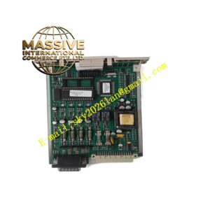
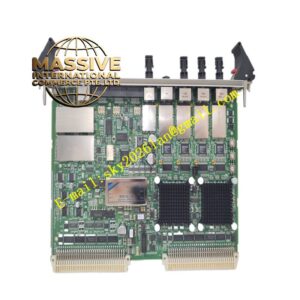
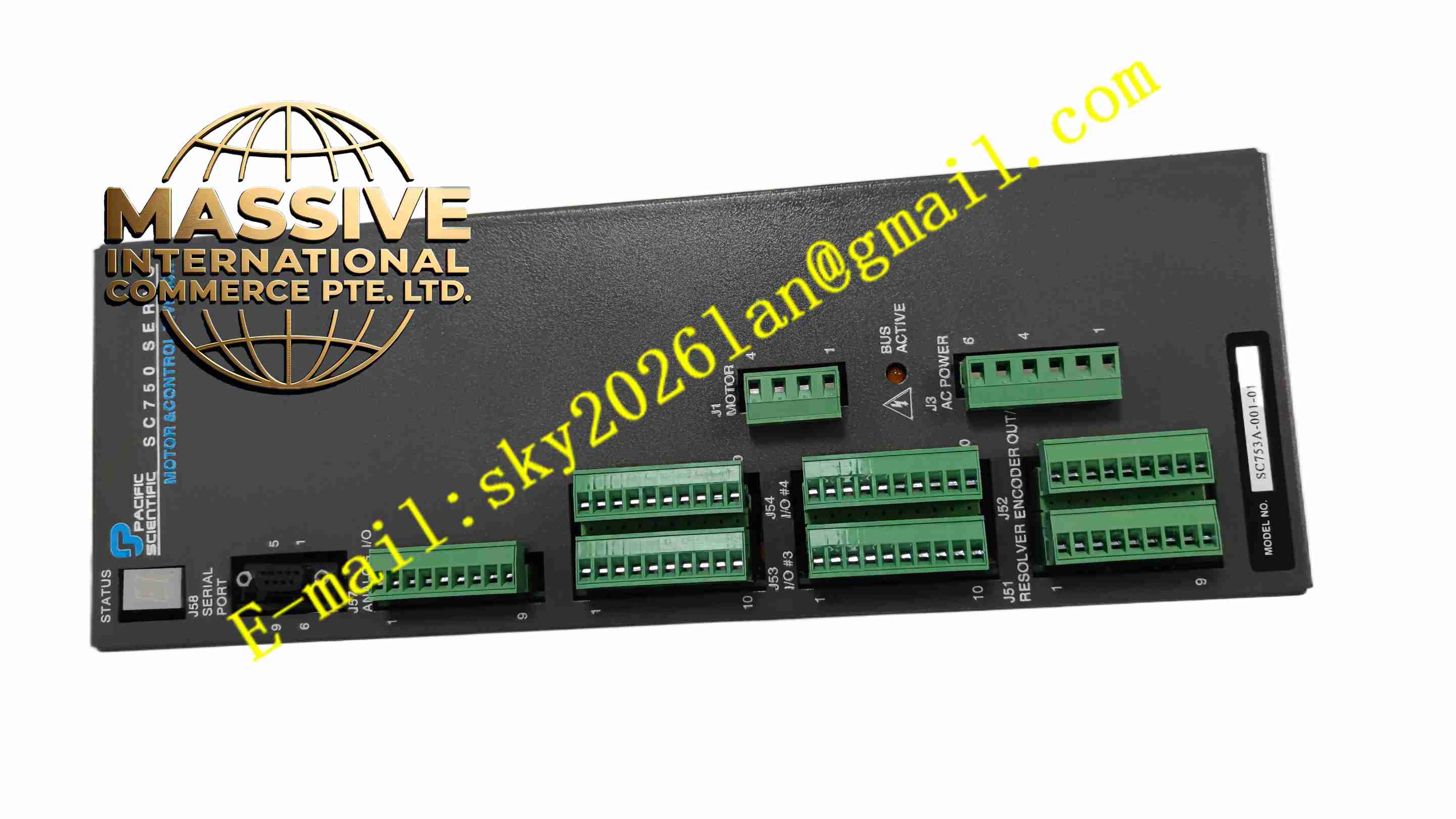
PACIFIC SCIENTIFIC SC753A-001-01
Technical Specifications Brand: Pacific Scientific Model: SC753A-001-01 Input Power: 115 VAC single phase, 50/60 Hz Continuous Output Current: 7.5 A RMS peak Feedback Interface: Incremental encoder, hall sensor Control Modes: Torque mode, velocity mode, position mode Analog Input: ±10 V analog command input Digital I/O: Configurable opto-isolated discrete inputs and outputs Operating Temperature: 0°C to +50°C Protection Grade: IP20 for cabinet installation Mounting: DIN rail or panel mounting
Functional Features Three optional closed-loop control modes for different motion application demands. Process incremental encoder and hall sensor signals to obtain rotor position and speed feedback. Accept ±10V analog command signal from upper motion controller. Programmable digital inputs for home switch, limit switch and servo enable signals. Programmable digital outputs for fault status, servo ready and in-position signal. Built-in hardware protection functions against overcurrent, overvoltage, undervoltage and overtemperature. Onboard potentiometers and DIP switches for basic parameter configuration without PC software.
Application Scenarios Packaging machine axis control, automated material handling equipment, textile machinery, small CNC machine feed axes, automated assembly stations, conveyor positioning systems.
Performance Parameters Fast current loop response for rapid torque adjustment. High resolution encoder feedback enables precise speed and position regulation. Instant hardware protection trigger when electrical parameters exceed rated threshold. Maintain stable speed output under load fluctuation. Low position tracking error for short stroke positioning tasks.
Material Composition Heat Sink Housing: Extruded aluminum alloy. Printed Circuit Boards: FR4 multilayer PCB with conformal coating. Core Electronic Components: IGBT power module, motion control processor, optocoupler, power electrolytic capacitors. Terminal Blocks: Screw-clamp plastic terminal blocks for power and signal wiring. Status Indicators: SMD LED lamps for power, fault and servo ready.
Structural Features Vertical compact enclosure with rear aluminum heat sink for power dissipation. Front panel separates high-current power terminals and low-voltage signal terminals. DIP switches and adjustment potentiometers locate on front panel for on-site configuration. LED status indicators display real-time operating state. Metal mounting holes on housing support panel mounting, compatible with DIN rail bracket.
Working Principle Single-phase AC input flows through rectifier circuit and converts to DC bus voltage. Control processor receives command signal from analog input or digital interface, calculates required three-phase motor current. PWM IGBT power stage outputs modulated current to servo motor windings. Encoder and hall sensor feed back rotor position and speed to close motion control loop. Internal monitoring circuit continuously measures current, voltage and temperature and triggers shutdown protection when fault occurs.
Installation Requirements Mount drive vertically inside ventilated electrical cabinet. Use shielded motor cable and shielded encoder cable, apply single-point shield grounding. Separate motor power wiring from low-level signal wiring to reduce electromagnetic interference. Set DIP switches and potentiometer parameters after wiring completion. Reserve clearance around aluminum heat sink to guarantee air convection cooling.
Usage Notes DC bus capacitors retain high voltage after power disconnection, wait for full discharge before opening cover. Do not apply input voltage exceeding 115 VAC rating. Verify encoder wiring phase sequence before power on to prevent motor runaway. Remove dust accumulated on heat sink periodically to avoid overheating. Backup parameter settings before modifying DIP switch configuration.