Description
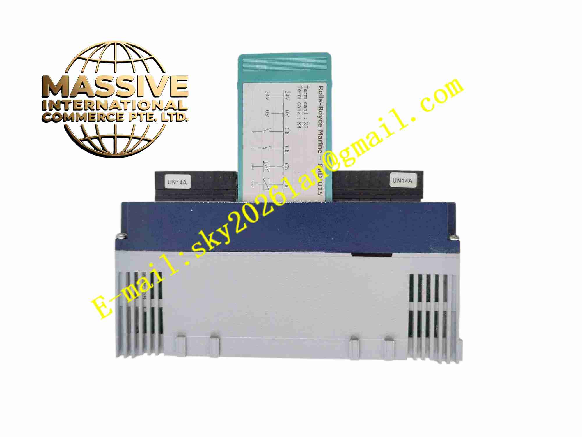
Rolls-Royce RRDIO15
Technical Specifications Brand: Rolls-Royce Model: RRDIO15 Power Supply: 24 VDC Input: 24 VDC digital binary input Output: Relay contact digital output Communication: Marine fieldbus Channel Isolation: Galvanic isolation between field and control side Protection Grade: IP20 cabinet installation Operating Temperature: -20°C ~ +70°C Humidity: 5% ~ 95% non-condensing
Functional Features Digital input acquisition for equipment status feedback signals. Relay contact output to actuate solenoid valves and auxiliary contactors. Channel diagnostics detect field wire break and short circuit. Galvanic isolation eliminates ground loop interference between field and control system. Front panel LED shows module power, bus communication and each channel state. Hardware withstands marine shock, vibration and salt mist environment. Self-test automatically runs after power reset.
Application Scenarios Marine thruster safety interlock control, vessel pump and valve status monitoring, offshore vessel machinery protection, ship fire and bilge system interlock, propulsion auxiliary equipment status collection.
Performance Parameters Fast response to discrete status change of field switches. High fault detection coverage of field wiring. Reliable bus communication under marine electromagnetic disturbance. Compliant with marine shock and vibration specification. Long-term stable operation under high humidity salt atmosphere.
Material Composition Front panel: flame retardant ABS plastic. PCB: FR4 multilayer industrial PCB with conformal coating. Core components: optocouplers, logic chips, sealed industrial relays. Backplane connector: gold plated edge connector. Indicator: SMD LED.
Structural Features Standard rack plug-in card form, rear gold finger connects to backplane fieldbus. PCB layout separates field power circuit and digital communication circuit. Each channel has independent opto-isolation circuit. Side latches support easy insertion and removal.
Working Principle Field 24VDC binary signals from limit switches and equipment auxiliary contacts enter module input terminals and pass opto-isolation circuit. Logic unit reads signal state and transmits data to central controller over fieldbus. The module receives control command from central controller and drives internal relay to switch contact state to control field actuators. When channel wiring fault appears, diagnostic signal uploads to central control station for alarm.
Installation Requirements Insert module into rack slot when power supply is off and lock latches. Shielded twisted pair cable used for field signal wiring, single point grounding. Signal cables routed separately from heavy power cables. Carry out channel wiring test after module configuration. Keep cabinet ventilation and heat dissipation space.
Usage Notes Voltage exceeding rated 24VDC must not be applied to input terminals. Check terminal tightness regularly under vessel vibration. Anti-static wristband required during disassembly and replacement. Verify channel configuration after new module installation. Keep cabinet interior dry to avoid circuit leakage.