Description
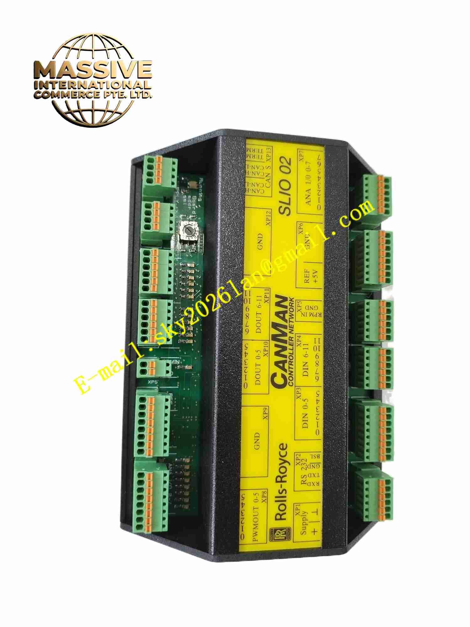
Rolls-Royce SLIO 02
Technical Specifications Brand: Rolls-Royce Model: SLIO 02 Module Type: Safety digital mixed I/O module Communication Interface: Internal safety bus for Rolls-Royce control system Mounting: Rack plug-in module Operating Temperature: -20°C to +70°C Humidity: 5% to 95% non-condensing Protection Grade: IP20 for cabinet installation Insulation: Galvanic isolation between field side and control bus Certification: Marine safety approvals for offshore and shipboard deployment
Functional Features Supports safety-related digital input and digital output signal transmission. Integrated hardware diagnostic circuits continuously monitor channel integrity and internal circuit health. Galvanic isolation separates field wiring from the safety control backplane to block surge interference. Front panel LED indicators display power status, running state and channel fault alarms. Dual-circuit safety architecture conforms to marine safety requirements. Supports hot swap operation for online module replacement without full system shutdown. Built-in short-circuit and overvoltage protection for each field channel.
Application Scenarios Ship propulsion safety monitoring, offshore platform safety interlock systems, marine emergency shutdown control, vessel auxiliary machinery status collection, marine fire and gas detection signal processing.
Performance Parameters High immunity against marine vibration, shock and electromagnetic interference. Fast fault detection and fault reporting for field wiring breakage and short circuits. Stable signal transmission under continuous 24-hour marine operation. Consistent safety response time for emergency interlock triggers. Isolation circuit prevents field-side electrical surges from damaging the safety main controller.
Material Composition Front Panel: Flame-retardant black reinforced plastic with LED indicator windows. PCB: FR4 multilayer printed circuit board coated with protective conformal coating. Core Components: Safety processor chips, optocoupler isolation devices, surge suppression diodes, bus transceivers. Back Connector: Gold-plated edge connector for rack backplane connection. Field Terminals: Tin-plated copper screw-clamp terminal blocks.
Structural Features Vertical plug-in card form factor for installation in standard control rack slots. Front panel houses status LED indicators and module locking latches. Rear gold finger connector mates with the rack safety backplane bus. PCB layout physically partitions low-voltage safety logic circuits and field signal circuits. Side locking latches secure the module firmly against mechanical vibration and shock.
Working Principle Field discrete sensor and switch signals feed into the module terminal block. Signals pass through optocoupler isolation circuits and are converted into logic-level digital signals for the onboard safety processor. The module transmits collected status data to the main safety controller via the backplane bus. When safety commands arrive from the main controller, the module drives output channels to actuate field safety equipment. Continuous self-diagnostic circuits check every channel and internal hardware state and raise fault alarms once abnormalities are detected.
Installation Requirements Cut off rack power supply before inserting the SLIO 02 module into the designated rack slot. Engage the side locking latches fully after module insertion to resist vibration. Use shielded twisted-pair cables for all field signal wiring. Route signal cables separately from high-power motor and power cables to reduce electromagnetic interference. Ground cable shields at a single defined grounding point. Verify all channel wiring connections and perform module diagnostic tests after power restoration. Maintain adequate ventilation clearance around the module inside the control cabinet.
Usage Notes Wear anti-static wristbands during module removal and replacement operations. Do not connect high-voltage signals to low-voltage I/O terminals. Inspect terminal screw tightness periodically in high-vibration marine environments. Prevent condensation and salt mist accumulation inside the control cabinet. Backup the safety control system configuration before performing module maintenance. Do not operate the module outside the rated temperature and humidity operating range.