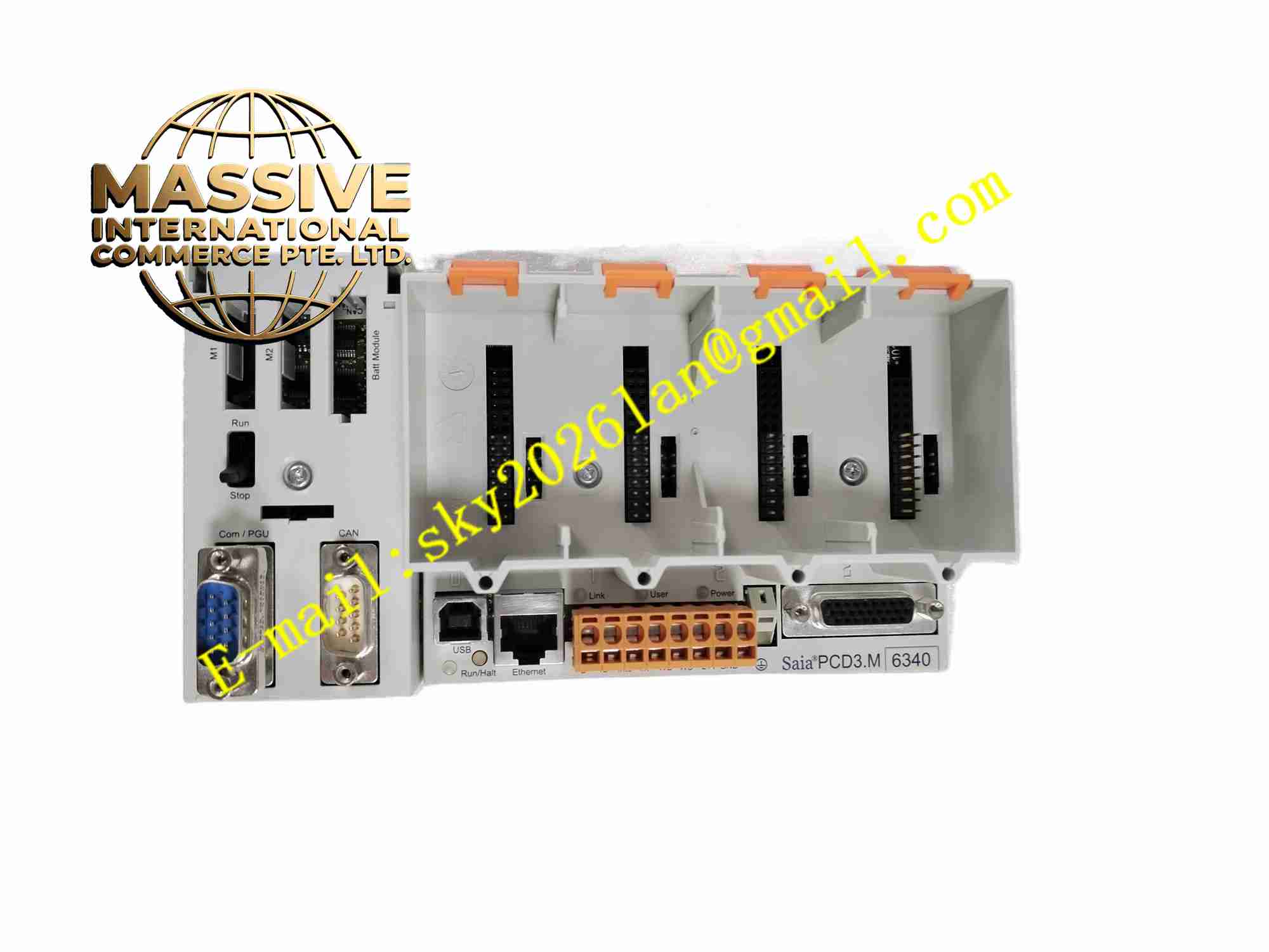
Description
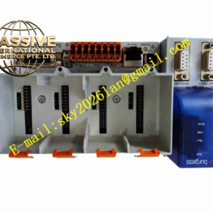
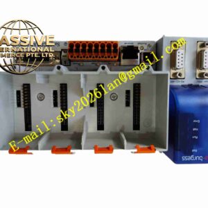
SAIA PCD3.M5540
Technical Specifications: Processor: 32-bit ARM Cortex-M3 Program memory: 1 MByte flash program storage RAM memory: 256 KB data RAM Power supply: 24 VDC Onboard I/O: 24 digital inputs, 16 relay digital outputs, 2 analog inputs, 2 analog outputs Communication interfaces: 10/100BASE-T Ethernet, PROFIBUS-DP slave up to 1.5 Mbps, USB 1.1, RS232, isolated RS485 Maximum expandable I/O: 1023 total I/O points, supporting up to 64 expansion modules Program execution speed: 0.1 µs per bit logic operation Operating temperature range: -20℃ ~ +60℃ Storage temperature range: -40℃ ~ +85℃ Relative humidity: 5% to 95%, non-condensing Mounting type: DIN rail mounting Protection grade: IP20 when installed inside control cabinet
Functional Features: Compliant with IEC 61131-3 international PLC programming standard, supporting IL, ST, FBD, LD programming languages. Native Ethernet port supports Modbus TCP/IP, HTTP web server, FTP file transmission and email alarm notification. Integrated PROFIBUS-DP slave interface for connection to PROFIBUS master controllers. Built-in web server for remote device status checking, parameter viewing and alarm browsing. Comprehensive data logging, event recording and timestamped alarm storage function. Real-time clock with battery backup to retain time and historical data after power loss. Hardware self-diagnosis to monitor CPU status, memory integrity, power supply and communication channel health. Expandable architecture to connect PCD3 series digital and analog I/O modules via system expansion bus. Support cybersecurity specification IEC 62443-3-3 for building and infrastructure control network.
Application Scenarios: Building HVAC automation system, district energy monitoring and control, lighting control for large commercial buildings, industrial plant auxiliary control, water treatment plant automation, tunnel ventilation control, energy metering and monitoring, renewable energy station local control.
Performance Parameters: Stable program cyclic execution under full I/O load without program crash or data loss. High immunity to electromagnetic interference meeting industrial and building automation EMC standards. Non-volatile memory retains user program and recipe data after power interruption. 24-hour continuous stable operation within rated temperature and humidity limits. High-precision real-time clock with millisecond-level timestamp for event sequence recording.
Material Composition: Main printed circuit board: Multi-layer high TG FR4 glass fiber epoxy PCB. Core electronic components: ARM Cortex-M3 microcontroller, flash memory chip, RAM chip, Ethernet PHY, PROFIBUS transceiver, isolated serial communication IC. Housing: Flame retardant grey polycarbonate plastic enclosure. Terminal blocks: PA66 flame retardant plastic screw terminals with tinned copper contacts. Relay units: Miniature industrial electromagnetic relays with gold-plated contacts.
Structural Features: Standard DIN rail snap-on rectangular housing structure. Front panel equipped with multi-color LED indicators for power, run, error and communication status. Top and bottom side terminal blocks for field I/O wiring and 24VDC power supply connection. Expansion bus connector on the right side to link additional PCD3 I/O expansion modules. Internal circuit partitioned into power supply area, CPU logic processing area, analog signal acquisition area and communication isolation area. Metal shielding layer on PCB to reduce internal signal crosstalk. Built-in battery compartment for real-time clock backup battery.
Working Principle: The module receives 24VDC control power supply from cabinet power source. After power-on self-test completes, the CPU loads user control program stored in flash memory and starts cyclic program execution. Digital and analog field signals are collected from onboard I/O channels or external expansion modules. The CPU executes logic calculation, PID regulation, threshold comparison and alarm judgment according to user program. Calculated output commands are sent to relay outputs and analog output channels to actuate field devices. Multiple communication ports exchange real-time data with SCADA, HMI or other PLC controllers. The real-time clock records time stamps for alarms and events. Continuous hardware self-monitoring circuit detects abnormal power, memory or communication faults and triggers fault LED indication.
Installation Requirements: Mount the PLC module onto standard 35mm DIN rail inside electrical control cabinet. Connect 24VDC power supply wiring to dedicated power terminals with correct polarity. Wire field sensors, actuators and measuring signals to corresponding I/O terminal blocks. Connect Ethernet cable or PROFIBUS bus cable to corresponding communication ports. Install PG5 engineering software on PC and establish programming connection via USB or Ethernet port. Download compiled user program and verify program operation after power on. Connect protective earth terminal to cabinet grounding busbar. Reserve air circulation clearance around module for heat dissipation. Separate analog signal cables and communication cables from high-power motor wiring.
Usage Notes: Wear anti-static wristband during module handling and program downloading. Verify wiring polarity of 24VDC power supply before powering on to avoid board damage. Backup user program and configuration data regularly before firmware upgrade or parameter modification. Check backup battery status periodically and replace battery before expiration to preserve clock and data. Do not operate module outside rated temperature and humidity range. Prevent conductive dust and liquid from entering terminal block area. Use shielded twisted pair cables for PROFIBUS and analog signal wiring.