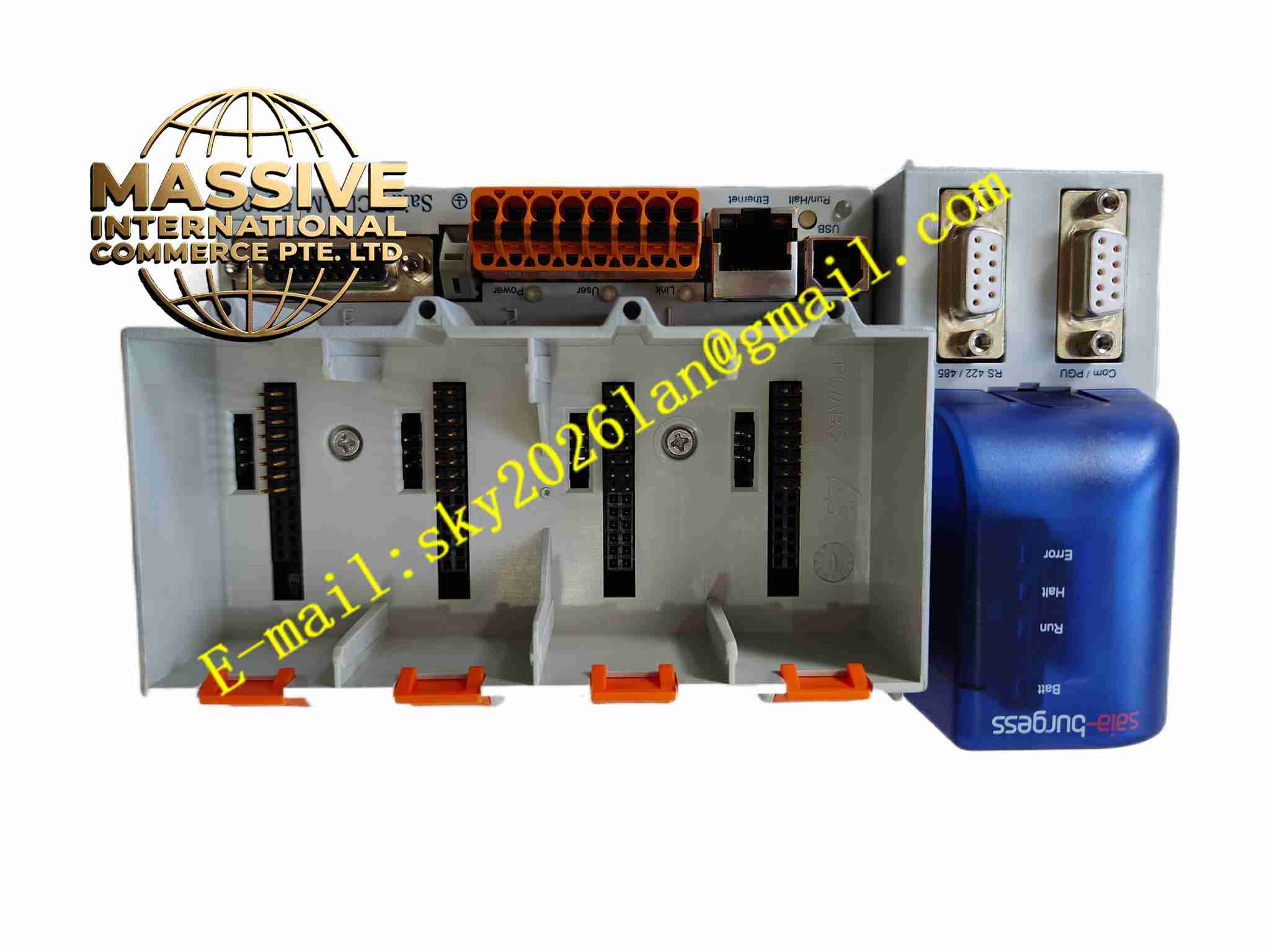
Description
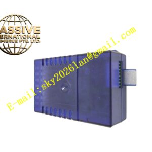
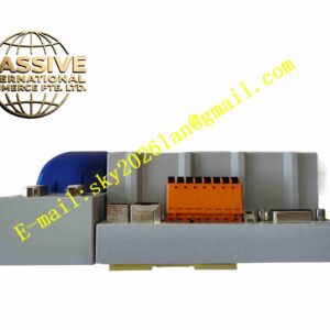
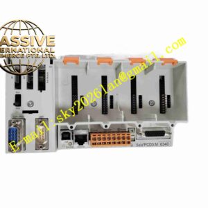
SAIA PCD3.A465
Technical Specifications
- Brand: Saia-Burgess Controls (SBC)
- Product Family: Saia PCD3 I/O Modules
- Module Type: Analog output module
- Model: PCD3.A465
- Function: Converts digital values into analog output signals
- System Compatibility: Saia PCD3 CPU and PCD3.Cxxx expansion bases
- Output Signal: Analog current or voltage signals depending on variant
- Channel Count: Multiple analog output channels; confirm exact count from the datasheet
- Resolution: High-resolution digital-to-analog conversion; exact resolution depends on the variant
- Isolation: Channel or group isolation may be provided depending on the hardware version
- Diagnostics: LED indicators and module status reporting via the PCD3 system
- Mounting: Installed in a I/O slot or expansion base
- Operating Temperature: Industrial temperature range; verify exact limits from the official documentation
Functional Features
- Precise analog output: Provides stable analog signals for process and motion control.
- Connects directly to the Saia automation platform.
- Configurable scaling: Output values can be scaled to match field device ranges.
- Diagnostic support: Reports module status and fault conditions to the CPU.
- LED indication: Shows channel activity and module health.
- Modular replacement: Can be replaced within the I/O structure when allowed by system rules.
- Industrial reliability: Designed for continuous operation in automation cabinets.
Application Scenarios
- Process control loops for temperature, pressure, flow, and level
- Control valve and actuator positioning
- Variable frequency drive speed reference output
- HVAC damper and valve control
- Energy management systems
- Test and simulation equipment
- Building automation and utility monitoring
- -based industrial control panels
Performance Parameters
- Output Type: Analog current or voltage depending on configuration
- Channel Count: Defined by the .A465 hardware variant
- Output Resolution: Determined by the module DAC design
- Update Rate: Depends on CPU scan time and I/O bus cycle
- Accuracy: Defined by the module specification; refer to the official datasheet
- Load Driving Capability: Must match the connected actuator or transmitter input impedance
- Diagnostic Coverage: Module status, channel status, and fault reporting through PG5
Material Composition
- Housing: Industrial plastic module enclosure
- PCB Assembly: Digital-to-analog converter, output driver, and bus interface circuits
- Terminal Interface: Screw or spring terminals for analog output wiring
- LED Indicators: Channel and module status LEDs
- Backplane Connector: Connects to the I/O bus or expansion base
Structural Features
- Plugs into a I/O slot.
- Front terminal access: Allows convenient wiring and maintenance.
- Compact I/O design: Saves space in control cabinets.
- Labelable terminals: Supports clear identification of output channels.
- Status LED row: Provides quick visual diagnosis.
- Modular architecture: Works with other CPU, communication, and I/O modules.
Working Principle
The CPU calculates control values based on the user program and sends them to the .A465 module over the internal I/O bus. The module converts these digital values into analog signals such as 0 to 10 V, 4 to 20 mA, or other supported ranges. The analog outputs then drive field devices such as control valves, inverters, actuators, or indicators. The module continuously monitors output status and reports faults such as open circuit, short circuit, or communication errors to the controller.
Installation Requirements
- Install the module in a compatible Saia base unit or .Cxxx expansion rack.
- Verify the 5 V I/O bus supply and 24 V field power where required.
- Connect analog output wiring according to the terminal diagram.
- Use shielded cables for analog signals to reduce interference.
- Keep analog wiring separated from power cables and switching loads.
- Configure output range, scaling, and diagnostics in Saia PG5.
- Check LED indicators and module status after downloading the configuration.
Precautions for Use
- Do not connect output signals to incompatible voltage or current levels.
- Do not short-circuit analog outputs unless the module explicitly supports short-circuit protection.
- Verify the exact output range, resolution, and channel count before commissioning.
- Avoid using the module for safety instrumented functions unless it is certified for such use.
- Replace the module only when the system allows safe hot-swapping.
- For exact electrical ratings, environmental limits, and wiring details, refer to the official Saia .A465 datasheet.