Description
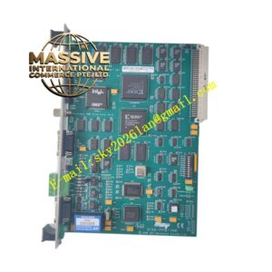
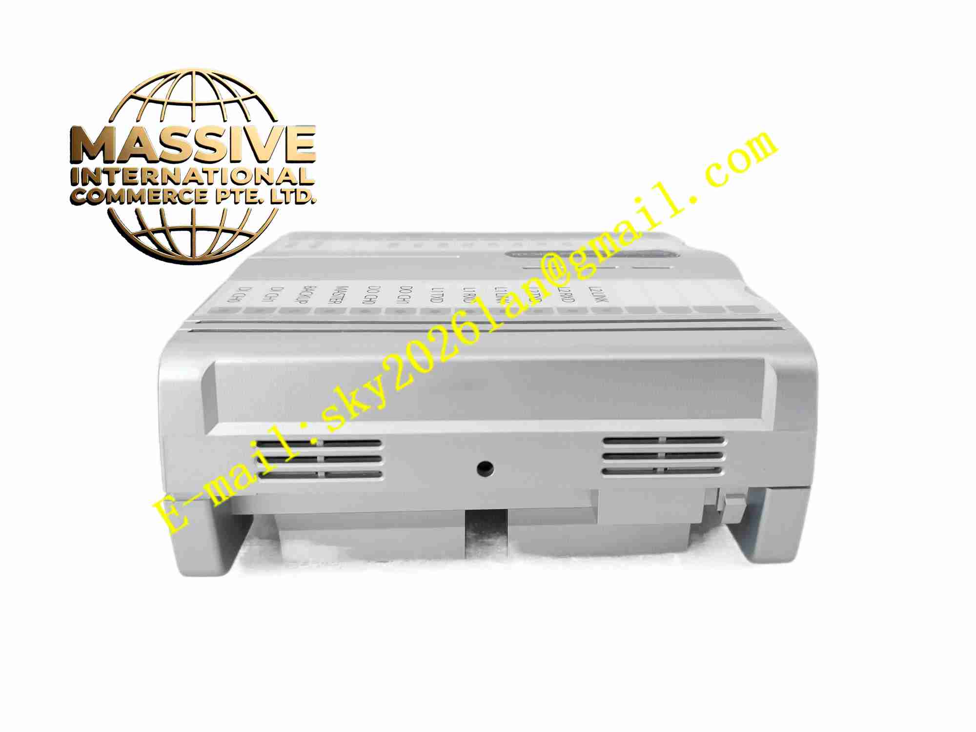
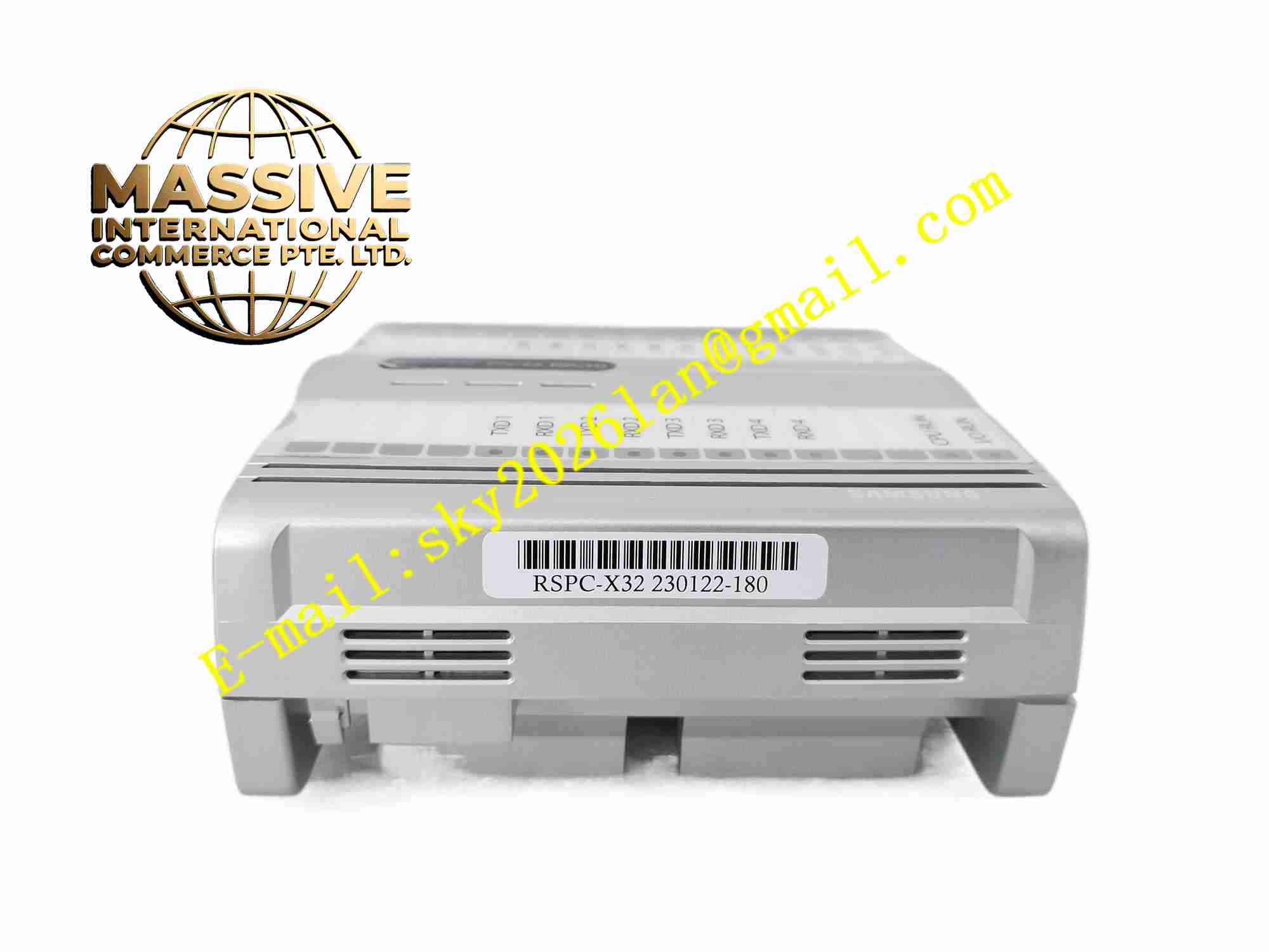
SAMSUNG RSPC-
Technical Specifications
- Product type: Remote digital I/O module
- Total channels: 32 digital channels
- Input/output configuration: Configurable per system definition
- Field bus: Industrial serial field bus
- Power supply: DC24V
- Input signal: DC24V discrete signal
- Output type: Transistor output
- Operating temperature: 0 °C to +60 °C
- Storage temperature: -20 °C to +70 °C
- Humidity: 5% to 95%, non-condensing
- Protection rating: IP20
- Installation: DIN rail mounting
- Indication: Per channel LED status indicator
Functional Features
- 32 channel digital I/O for factory automation
- High speed field bus communication with main PLC
- Per channel LED status indication
- Overload and short circuit protection on output channels
- Galvanic isolation between field side and internal logic
- DIN rail quick installation
- Modular expansion capability
- Diagnostic reporting for channel fault
- Fast response for discrete production signals
- Compact design to save cabinet space
Application Scenarios
- Automotive assembly production line
- Conveyor material handling control
- Packaging machine signal collection
- Automated warehouse bin sensor monitoring
- General factory discrete automation control
Materials and Construction
- Housing: Flame retardant engineering plastic
- PCB: FR4 printed circuit board
- Semiconductors: Photo coupler for isolation, power transistor for output
- Terminal blocks: Screw type anti-vibration terminals
- LED: Status indicator diodes
- Mounting clip: Plastic DIN rail clip
Structural Features
- Narrow rectangular DIN rail plastic housing
- Front panel LED indicators for each channel
- Top and bottom screw terminal blocks for field wiring
- Internal logic circuit, isolation devices and output drivers
- Built-in DIN rail spring clip on rear side
- Compact closed plastic enclosure
Working Principle Field sensors and limit switches connect to digital input terminals. Optocouplers isolate field 24V signals and transfer status to internal logic chip. The module communicates input status to main PLC over field bus. When receiving output commands from PLC, internal transistors switch 24V DC to drive field actuators. Diagnostic circuit monitors output short circuit and overload, triggering fault indication when abnormal state appears.
Installation Requirements
- Snap module onto standard 35mm DIN rail inside control cabinet
- Connect DC24V power supply with correct polarity
- Wire field sensors and actuators to corresponding terminals
- Configure module station address on field bus
- Keep ambient temperature between 0 °C and +60 °C
- Separate signal wiring from high power AC cables
- Connect cabinet protective earth
Precautions
- Do not connect AC voltage to digital I/O terminals
- Verify field bus address uniqueness in network
- Do not exceed maximum load current per output channel
- Store spare modules in dry environment
- Check terminal screw tightness periodically
- ESD protection required during module replacement
- Avoid oil and dust accumulation inside cabinet