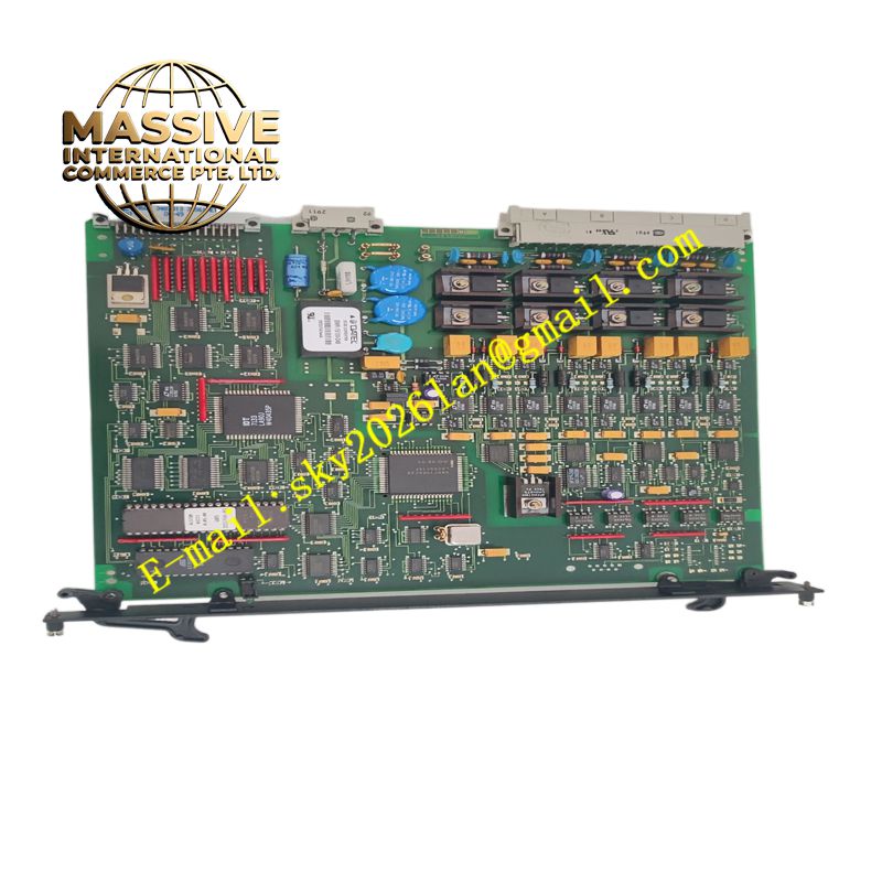
Description
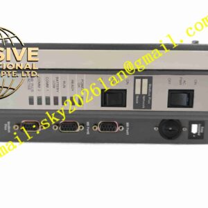
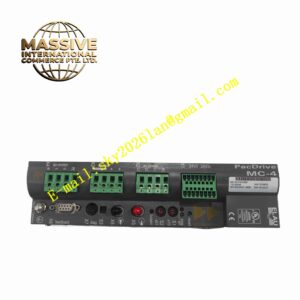
Schneider AS111-2
Technical Specifications Supports 4-20mA analog current signal input and output; galvanic isolation between input side and output side; isolation voltage 1500V AC; 24V DC auxiliary power supply; operating temperature 0°C to +60°C; IP20 protection; signal transmission accuracy ±0.1% full scale.
Functional Features Receive standard analog signals from field transmitters. Achieve electrical isolation between field instrument side and control cabinet side to eliminate ground loop noise. Convert input analog signals into stable standard analog output signals for control system I/O modules. Maintain linear signal transmission within the full working range. Detect internal power supply abnormality and output abnormal signal state when faults occur.
Application Scenarios Chemical industry distributed control systems, power plant instrument signal transmission, metallurgical plant measurement loops, wastewater treatment instrument signal isolation, building automation analog signal conversion.
Performance Parameters High linearity of signal transmission; low signal attenuation during isolation transmission; stable performance under wide ambient temperature variation; high common-mode interference rejection.
Material Composition Internal circuit PCB uses FR-4 flame-retardant multilayer board; signal processing chips are high-precision operational amplifiers; isolation components adopt reinforced optocoupler circuits; outer shell is flame-retardant ABS plastic; terminal blocks use nickel-plated copper contacts.
Structural Characteristics Compact DIN rail mounting rectangular housing. Top and bottom terminal blocks are arranged separately for input signal, output signal and auxiliary power wiring. Front panel carries LED indicator for power status. Internal circuit divides input isolation zone and output drive zone.
Working Principle The input analog signal enters the isolation circuit and converts into isolated digital signal inside the unit. The circuit reconstructs the analog signal on the output side without direct electrical connection between input and output circuits. The reconstructed standard analog signal transmits to the control system I/O module to complete isolated signal transmission.
Installation Requirements Mount the unit on standard DIN rail inside the electrical control cabinet. Wire field transmitter signal to input terminals and wire output terminals to control system analog module. Connect 24V DC auxiliary power supply to corresponding power terminals. Conduct full-range signal test after wiring completion.
Precautions for Use Do not mix signal wiring and high-power motor wiring in the same cable trunking. Do not apply overvoltage to signal terminals. Keep the unit away from heat sources such as power resistors and frequency converters. Disconnect auxiliary power supply before modifying wiring.