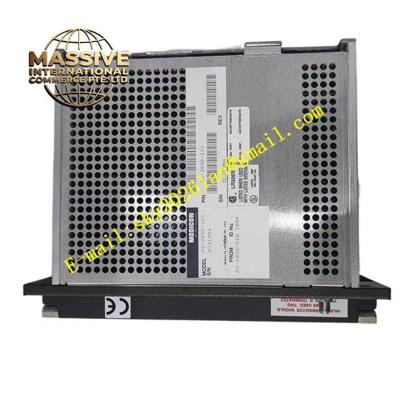
Description
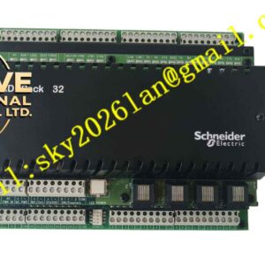
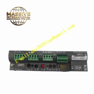
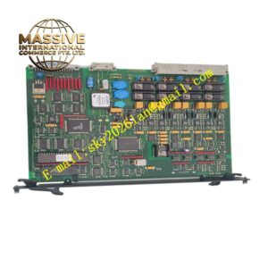
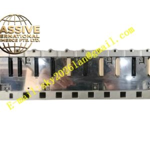
Schneider AS-J890-101-1004
Technical Specifications Remote I/O bus interface; supports Schneider dedicated remote I/O protocol; 24V DC module operating power supply; opto-isolation between bus interface and local I/O backplane; isolation withstand voltage 1500V AC; operating temperature 0°C to +60°C; IP20 protection rating.
Functional Features Serve as communication bridge between remote I/O rack and central control rack CPU. Forward input data collected by local I/O modules on the remote rack to the main controller. Transmit control commands issued by the central CPU to local output modules on the remote rack. Conduct self-diagnosis of bus communication status and local backplane hardware. Upload bus disconnection and rack power failure fault alarms to the main control system. Support remote rack address configuration through hardware switch or software setting.
Application Scenarios Large factory distributed production line control, long-distance material handling system, water plant distributed instrument control, mining remote signal collection, large warehouse automation control system.
Performance Parameters Deterministic remote data transmission cycle; automatic communication fault diagnosis; fast link recovery after temporary bus interruption; stable data transmission over long bus distances.
Material Composition Main PCB uses FR-4 flame-retardant multilayer printed circuit board; communication processing chips are industrial semiconductors; isolation components adopt optocoupler circuits; backplane gold finger contacts use gold-plated copper alloy; module housing is flame-retardant thermoplastic resin; terminal blocks use nickel-plated copper contacts.
Structural Characteristics Vertical plug-in module installed in the dedicated master slot of remote I/O rack. Front panel equipped with LED indicators for power, bus communication and fault status. Rear gold finger connector connects to remote rack local backplane. External bus terminal blocks are used for remote communication cable wiring. Side buckle fixes the module on the rack.
Working Principle The module receives data frames sent by the central CPU over the remote bus, parses control commands and distributes commands to local I/O modules via the rack backplane. It collects input data from local I/O modules, packages data into bus protocol frames and sends frames back to the central CPU. The onboard diagnostic circuit monitors bus signal quality and local rack hardware state continuously.
Installation Requirements Cut off power supply of the remote rack before module installation. Insert the adapter module into the dedicated master slot and lock the side buckle. Connect remote bus communication cable to bus terminals and set remote rack address. Configure remote I/O mapping in the central rack programming software. Test bidirectional data communication between remote rack and central CPU after power-on.
Precautions for Use Install matching terminal resistors at both ends of the remote bus cable. Use shielded twisted-pair cables for remote bus wiring. Do not lay bus cables in parallel with high-voltage power cables. Record rack address and configuration parameters for backup.