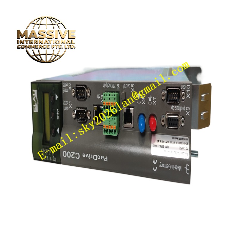
Description
Schneider C2001011100
Technical Specifications Rated working voltage range 24V DC to 240V AC. Industrial-grade operating temperature spans -25°C to +70°C. Standard dimension for industrial cabinet mounting. Built-in overvoltage, overcurrent and overtemperature protection circuits. Support standard industrial electrical signal input and output. Comply with IEC international electrical safety standards. Front panel reaches IP40 protection grade after installation. Adopt anti-surge and anti-electromagnetic interference design. Support long-term continuous full-load operation.
Functional Features Collect and process industrial electrical signals in real time. Monitor circuit operating status and activate protection when electrical parameters exceed limits. Deliver stable logic control output for peripheral electrical actuators. Execute internal self-diagnosis to identify overload, short circuit and voltage faults. Maintain steady operation without frequent breakdown. Possess strong immunity against electromagnetic noise from inverters and servo motors. Support manual and automatic working modes for production and maintenance scenarios.
Application Scenarios Electrical control cabinets for industrial automation production lines, low-voltage distribution systems of commercial buildings, supporting control circuits of mechanical equipment, electrical systems of environmental protection water treatment facilities, power control units of logistics conveying equipment, automatic control loops for small and medium industrial machinery.
Performance Parameters Deliver high-precision signal processing and zero-delay response for regular control signals. Maintain stable output under prolonged full-load operation. Feature low internal power consumption and high energy efficiency. Keep consistent control performance under voltage fluctuation in factory power grids.
Material Composition Main printed circuit board uses FR-4 flame-retardant multilayer substrate. Signal processing chips are industrial semiconductors. Enclosure is made of high-strength flame-retardant thermoplastic. Terminal contact springs adopt nickel-plated copper alloy. Internal insulation components use flame-retardant composite materials.
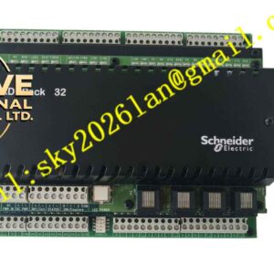
Structural Characteristics Compact rectangular housing suitable for cabinet installation. Front panel carries LED indicators for power, running status and fault alarm. Screw terminals on upper and lower edges are reserved for power and signal wiring. Internal layout separates power circuits and weak signal circuits to reduce interference. Side fixing lugs are used for fastening on mounting plates or DIN rails.
Working Principle Field electrical signals enter the module’s signal conditioning circuit and get filtered. The onboard microprocessor analyzes signal data and executes preset logic programs. Output drive circuits send control signals to external contactors or indicators. Internal monitoring circuits continuously sample voltage, current and temperature values. Protection mechanisms activate immediately once parameters cross rated thresholds.
Installation Requirements Mount the module firmly on DIN rail or mounting plate inside the control cabinet. Connect power supply and field signal cables to corresponding terminals following official wiring diagrams. Verify wiring tightness and insulation integrity after wiring. Configure logic parameters through supporting configuration software. Complete power-on test and signal response verification before putting into service.
Precautions for Use Do not apply voltage beyond the rated working range to signal terminals. Keep the cabinet well ventilated to avoid heat accumulation around the module. Separate signal cables from high-current power cables during wiring. Cut off the input power supply before modifying wiring or replacing the module. Conduct regular inspection of terminal tightness and dust removal.