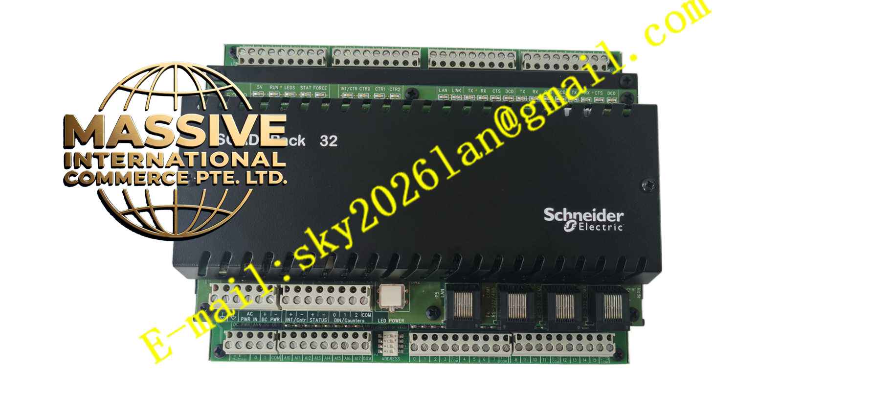
Description
Schneider TBUP4-105-01-00
Technical Specifications Screw terminal blocks for field wiring; Backplane bus interface; Power distribution circuit for I/O module; Operating temperature -5°C to +60°C; DIN rail mounting; Supports hot swap of top I/O module; Channel marking printed on base housing.
Functional Features Mechanical mounting platform for compatible plug-in I/O modules; Field wiring terminal blocks integrated on base; Transfers backplane bus signal and module supply power; Hot swap support allows I/O module replacement without powering down rack; Printed marking identifies each signal channel; Cable strain relief structure; Isolation between field wiring and backplane circuit.
Application Scenarios Factory automation PLC control cabinet; Packaging machine I/O control; Conveyor system control panel; Water treatment plant PLC system; Material handling automation equipment; Building industrial automation control.
Performance Parameters Bus signal transmission on base remains stable; Terminal contact resistance maintains low value; Mechanical locking structure holds I/O module firmly; Hot swap operation does not affect other rack modules; Withstands thermal cycling in industrial cabinet environment.
Material Composition Flame-retardant plastic base housing; Tin-plated brass terminal conductors; Steel terminal clamping screws; Internal printed circuit traces for bus and power; Plastic locking latch for I/O module; Metal DIN rail clip.
Structural Features Flat base body designed to install on DIN rail; Top locking mechanism for plug-in I/O module; Front side screw terminals for field wiring; Back side contact pins for rack backplane connection; Printed channel marking on front panel.
Working Principle The terminal base is fixed on DIN rail and connected to PLC rack backplane. Field cables from sensors and actuators are wired to front screw terminals. Internal conductive traces transmit power and bus signals from backplane to the I/O module installed on top of base. Signals between I/O module and field devices pass through terminal base wiring terminals. The locking latch holds the electronic module securely, and supports releasing the latch to remove module while base remains powered and wired.
Installation Requirements Snap base onto standard DIN rail and lock clip; Tighten field wiring terminal screws to specified torque; Use stranded copper wires for field connection; Separate low level signal wiring from high power cables; Ensure reliable protective earth connection for cabinet.
Precautions for Use Confirm module compatibility before placing I/O module onto base; Do not apply overvoltage to field terminals; Check terminal screw tightness periodically; Keep base surface free from conductive dust; Verify hot swap permission before removing I/O module while powered.