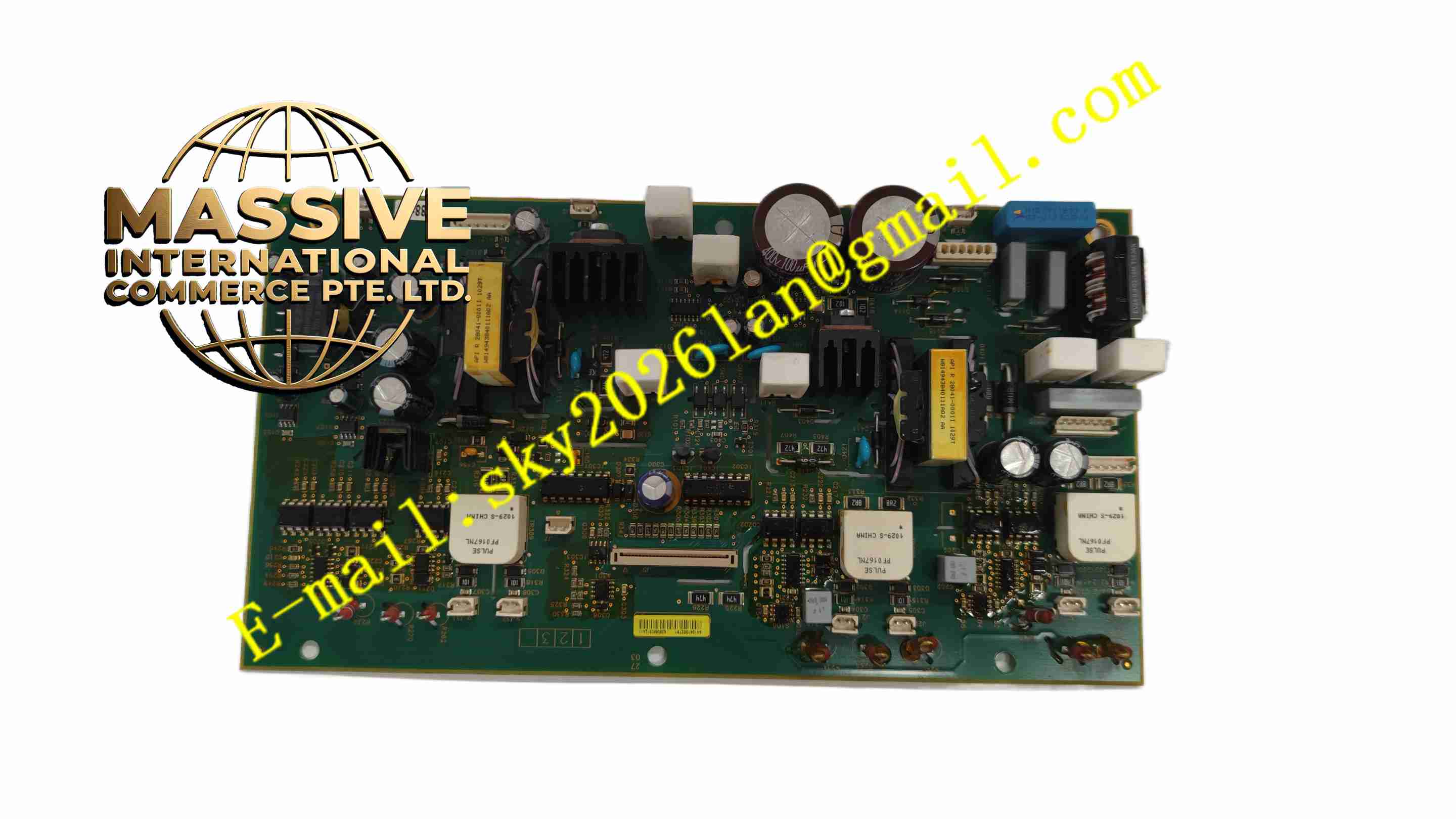
Description
Schneider VX5G48C32Q
Technical Specifications: Rated operating voltage: 480V class Rated current: 320A Power device type: IGBT power transistor Cooling method: Liquid cooling DC bus input: Three-phase rectified DC voltage Overload capability: Heavy duty overload rating Operating temperature: 0℃ to +60℃ Protection functions: Overcurrent, overvoltage, undervoltage, overtemperature Mounting: Chassis installation inside drive cabinet Certifications: CE, UL
Functional Features: Three-phase IGBT power conversion to generate adjustable frequency AC for motor drive. Integrated current sampling for output current monitoring and protection. Gate drive circuit receives PWM signal from drive control board to switch IGBTs. Built-in temperature sensor to monitor power semiconductor temperature. Multiple hardware protection functions activate immediately upon fault detection. Liquid cooling interface provides efficient heat dissipation under heavy load. Fault signal feedback to drive controller for fault logging and safe shutdown.
Application Scenarios: Large industrial fan and pump control, extruder main motor drive, metallurgy rolling mill motor, mining conveyor drive, marine large auxiliary motor, heavy machinery main drive system.
Performance Parameters: High switching frequency for smooth motor current waveform. High overload withstand capability for heavy duty starting condition. Low thermal resistance design with liquid cooling system. Fast hardware overcurrent protection response. Stable output torque across full motor speed range.
Material Composition: Copper base insulated metal substrate PCB. High power IGBT semiconductor chips. Aluminum alloy liquid cooling heat sink. Gate drive optocoupler and power resistors. High current copper busbars. High voltage plastic insulated terminal blocks.
Structural Features: Integrated power module assembly with built-in heat sink. High current bus bar terminals for DC bus and three-phase motor output. Signal connector for PWM control signal and temperature feedback. Sealed power compartment to prevent dust contamination. Temperature sensor mounted directly on IGBT substrate. Compact assembly structure for installation inside variable speed drive cabinet.
Working Principle: DC bus high voltage supplies the IGBT power module. Control board sends PWM gate drive signals to module gate drive circuit. IGBT components switch on and off according to PWM command, converting fixed DC voltage to variable frequency three-phase AC voltage. Current sampling circuit continuously measures output current. Temperature sensor monitors IGBT junction temperature. When overcurrent, overvoltage or overtemperature occurs, hardware protection circuit blocks IGBT gate signal instantly and sends fault signal back to drive controller. Liquid coolant flows through heat sink to remove heat generated by power semiconductors.
Installation Requirements: Install module into designated position inside Schneider variable speed drive cabinet. Connect DC bus and motor output busbar with specified torque. Connect liquid cooling pipeline and complete leakage test. Route low voltage signal cable separately from high power busbar. Tighten signal connector locking mechanism. Verify cooling liquid flow rate and pressure before power energization.
Usage Notes: Confirm liquid cooling medium specification matches module requirement. Check busbar insulation surface for damage before power on. Do not apply voltage exceeding rated DC bus limit. Release residual DC bus charge before opening drive cabinet cover. Inspect cooling pipeline regularly for leakage. Replace module only after complete power isolation and discharge.