Description
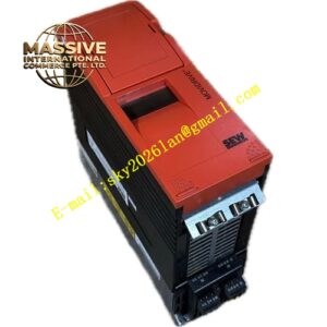
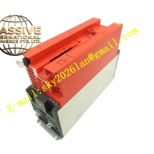
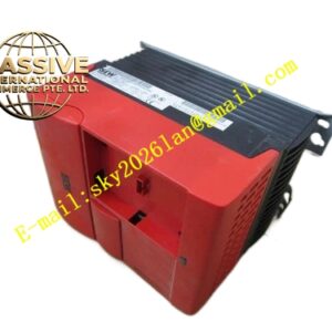
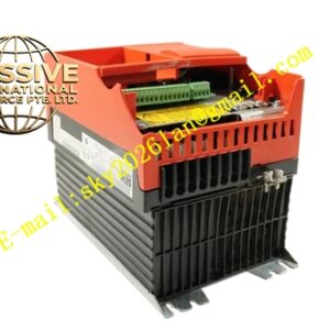
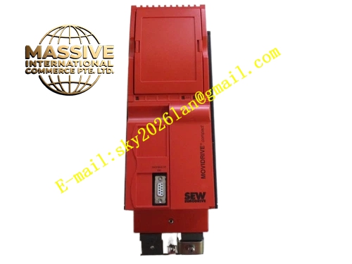
SEW MCF41A0075-5A3-4-00
Technical Specifications:
- Brand: SEW-EURODRIVE
- Series: MOVIDRIVE compact MCF41A
- Recommended Motor Power: 7.5 kW
- Input Voltage: 3-phase AC 380–500V, 50/60 Hz
- Control Mode: VFC (Voltage Mode Flux Control), V/f Control
- Encoder Feedback: Not required (open-loop)
- Operating Quadrants: 4Q (with brake chopper)
- Line Filter: Radio interference suppression Class A installed
- Protection Rating: IP20
- Operating Temperature: 0°C to +50°C
- Certifications: CE, UL
- EMC Standard: EN 61000-4 (Class A)
Functional Features:
- VFC Control Mode: Voltage-controlled field-oriented control achieving at least 150% torque at standstill (with encoder) or down to 0.5 Hz (without encoder)
- IPOS+ Integrated Positioning System: Autonomous motion sequence control within the inverter
- PROFIBUS-DP Communication: Integrated fieldbus interface for seamless integration into industrial automation networks
- Comprehensive Protection Suite: Overcurrent, overvoltage, undervoltage, overheating, phase loss, and ground fault detection
- Modular Design: Compact form factor with removable connection unit for efficient maintenance
- System Bus (SBus): Standard networking interface for multi-drive coordination via MOVILINK protocol
- Energy-Efficient Operation: Automatic voltage optimization under light load conditions
Application Scenarios:
- Medium-duty conveyor and material handling systems
- Pump and fan variable speed drives
- Machine tool spindle control
- Packaging and printing machinery
- Chemical process agitation
- Water treatment systems
Performance Parameters:
- Torque Capability: At least 150% torque at standstill (with encoder), at least 150% torque down to 0.5 Hz (without encoder)
- Output Frequency Range: 0–550 Hz
- Speed Control Accuracy: ±0.5% (open-loop VFC mode)
- Overload Capacity: 150% rated current for 60 seconds
- Dynamic Response: Optimized for standard industrial load profiles
Material Composition:
- Industrial-grade IGBT power modules
- Coated circuit boards for dust and moisture protection
- Aluminum heat sink for thermal dissipation
- Integrated EMC filter components
- Steel enclosure with powder-coated finish
Structural Features:
- Compact cabinet-mount form factor
- Removable connection unit with separable power and motor terminals
- X1: Power supply connection (1/L1, 2/L2, 3/L3)
- X2: Motor connection (4/U, 5/V, 6/W)
- X3: Braking resistor connection (8/+R, 9/–R) with PE connection
- X10: Electronics terminal strip for control signals
- TERMINAL slot for DBG keypad or USS21A/USB11A option
- LED status and diagnostic indicators
- Shield clamp for power section grounding
Working Principle:
The inverter converts AC input to DC through a three-phase rectifier, stores energy in DC bus capacitors, and synthesizes a variable-frequency PWM output through IGBT switching. The VFC algorithm continuously calculates the complete motor model to regulate magnetic flux and electromagnetic torque independently, achieving high-efficiency operation across the full speed range.
Installation Requirements:
- Mount vertically in a control cabinet with adequate ventilation
- Maintain minimum clearance above and below the unit for airflow
- Use shielded power and motor cables with proper 360° shield grounding
- Ensure motor cable phase sequence matches U-V-W terminal markings
- Connect braking resistor to dedicated brake terminals when dynamic braking is required
- Ambient temperature must remain within 0°C to +50°C range
- Humidity must be maintained between 30% and 60% RH
Usage Notes:
- Perform motor initialization when connecting a new motor
- Use MOVITOOLS MotionStudio software for parameter configuration and commissioning
- Verify power supply voltage stability within ±10% tolerance before operation
- Never connect or disconnect motor cables while the inverter is energized
- Monitor fault codes via the integrated LED display or MOVITOOLS software
- Clean heat sink dust regularly; accumulation exceeding 2 mm thickness requires cleaning
- Verify grounding resistance is less than 1 Ω