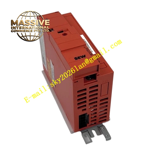
Description
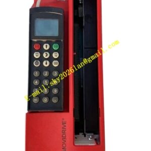
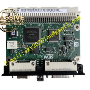
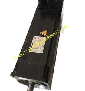
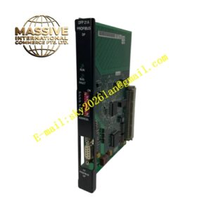
SEW MCV41A0022-5A3-4-00
Technical Specifications:
- Brand: SEW-EURODRIVE
- Series: MOVIDRIVE compact MCV41A
- Size: Size 1
- Recommended Motor Power: 2.2 kW (VFC mode)
- Supply Voltage: Three-phase AC 380–500V, 50/60 Hz
- Control Modes: VFC + CFC
- Encoder Feedback: Required for CFC mode
- Operating Quadrants: 4Q (integrated brake chopper)
- Fieldbus Interface: PROFIBUS-DP (integrated)
- Radio Interference Suppression: Class A filter built-in
- Protection Class: IP20
- Operating Temperature: 0°C to +50°C
- Certifications: CE, UL/cUL
Functional Features:
- Dual-Mode Control: VFC open-loop and CFC closed-loop vector control
- Field-Oriented Control (FOC): High torque at low speeds
- IPOS+ Integrated Positioning: Autonomous motion sequence control
- Comprehensive Protection: Overcurrent, overvoltage, undervoltage, overheating, ground fault, motor stall
- STO Safety Function: SIL3/PLe compliant
- Modular Removable Design: Independently replaceable components
- SD Card Parameter Copy: Batch commissioning support
- Built-in PID Controller: Closed-loop process control
- PROFIBUS-DP Communication: Integrated fieldbus interface
Application Scenarios:
- Small-to-medium fan and pump variable speed control
- Conveyor belt systems
- Mixing and blending equipment
- Textile machinery
- Packaging machines
- HVAC systems
- Water treatment and dosing systems
- Light material handling
Performance Parameters:
- Overload Capacity: 150% rated current for 60 seconds
- Output Frequency Range: 0–500 Hz
- PWM Switching Frequency: Up to 32 kHz
- Speed Range: -5000 to +5000 rpm
- Speed Resolution: 0.2 rpm
- Voltage Tolerance: ±10% mains voltage fluctuation
Material Composition:
- Industrial-grade IGBT power modules
- Conformal-coated circuit boards
- Aluminum heat sink
- Integrated EMC filter components
- Steel housing with powder-coated finish
Structural Features:
- Compact cabinet-mount structure (Size 1)
- Modular removable design
- Power supply terminals (L1, L2, L3) — separable X1
- Motor output terminals (U, V, W) — X2
- Braking resistor terminals (+R, -R) and PE — separable X3
- DC link connection (-U) — X4
- Electronics terminal strip X10
- PROFIBUS-DP (9-pole Sub-D) — X30
- Encoder simulation / external encoder (9-pole Sub-D) — X14
- Motor encoder input (9-pole Sub-D) — X15
- DBG keypad / option slot
- LED status and diagnostic indicators
- Shield clamp for power section grounding
Working Principle:
The inverter converts AC input to DC via a three-phase rectifier, stores energy in DC bus capacitors, and synthesizes variable-frequency PWM output through IGBT switching. VFC mode operates without encoder feedback using an internal motor model; CFC mode uses encoder feedback for closed-loop current vector control with real-time flux and torque decoupling.
Installation Requirements:
- Vertical cabinet mounting with adequate ventilation
- Minimum clearance above and below for airflow
- Shielded power and motor cables with 360° grounding
- Phase sequence matching U-V-W terminals
- Braking resistor connection for dynamic braking
- Ambient temperature 0°C to +50°C
- Encoder cable connection for CFC mode
- PROFIBUS-DP cable to X30
Usage Precautions:
- Execute motor initialization after motor connection
- Commission via MOVITOOLS MotionStudio software
- Verify supply voltage within ±10% tolerance
- Never connect/disconnect motor cables under power
- Monitor fault codes via LED or MOVITOOLS
- Regular heat sink cleaning
- Grounding resistance below 1 Ω
- Wait 5 minutes after power-off before maintenance
- Derate 20% at 500V supply