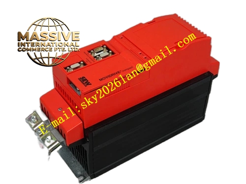
Description
SEW MDV60A0022-5A3-4-00
Technical Specifications:
- Brand: SEW-EURODRIVE
- Series: MOVIDRIVE MD 60A
- Type: MDV (VFC/CFC operating modes)
- Recommended Motor Power: 2.2 kW (constant load) / 3.0 kW (variable torque)
- Supply Voltage: 3-phase AC 380–500V, 50/60 Hz
- Operating Modes: VFC (open-loop) and CFC (closed-loop with encoder)
- Quadrants: 4Q (with brake chopper)
- Input Filter: Integrated
- Protection Class: IP20
- PWM Frequency: Adjustable 4/8/12/16 kHz in VFC mode; fixed at 8 kHz in CFC mode
- Speed Range: -5000 to +5000 rpm
- Speed Resolution: 0.2 rpm
Functional Features:
- Dual Operating Modes: Supports both VFC (open-loop voltage flux control without encoder) and CFC (closed-loop current flux control with encoder) for flexible application matching
- Four-Quadrant Operation: Built-in brake chopper for regenerative braking and rapid deceleration
- Integrated Input Filter: Ensures EMC compliance and reduces electromagnetic interference
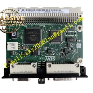
- Modular Option Card Slots: Two option card slots for fieldbus modules, digital I/O expansion, and encoder interfaces
- IPOSplus Motion Controller: Integrated programmable positioning and logic control
- Comprehensive Protection Suite: Overcurrent, overvoltage, undervoltage, overheating, ground fault, and motor stall protection
- PID Controller: Built-in PID controller for process control applications
Application Scenarios:
- Conveyor systems with moderate speed control requirements
- Fan and pump drives with variable torque loads
- Packaging machinery
- Textile machinery
- Light-duty material handling equipment
- Mixing and agitation systems
Performance Parameters:
- Continuous Output Current: 5.5 A (VFC mode, 125% load) / 5.0 A (CFC mode, 100% load) at 400V
- Output Frequency Range: 0–500 Hz
- Overload Capacity: 150% rated current for 60 seconds
- Speed Control Accuracy: Better than 0.5% in VFC mode; high precision in CFC mode with encoder
- PWM Switching Frequency: Adjustable 4/8/12/16 kHz (VFC); fixed 8 kHz (CFC)
Material Composition:
- Industrial-grade IGBT power modules
- Conformal-coated control circuit boards
- Aluminum heat sink with forced air cooling
- Integrated EMC/RFI filter components
- Steel housing with powder-coated finish
Structural Features:
- Compact cabinet-mount housing with modular design
- Power supply input terminals (L1, L2, L3)
- Motor output terminals (U, V, W)
- Braking resistor terminals (+R, -R)
- Two option card PCB slots (OPTION1 and OPTION2)
- Control card slot (CONTROL)
- Signal terminal connectors (X10–X13)
- Power shield clamp for cable grounding
- LED status and diagnostic indicators
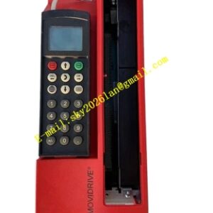
- DBG keypad interface
Working Principle:
The inverter converts three-phase AC input power through a rectifier stage into DC bus voltage, which is smoothed by capacitors. The IGBT inverter stage synthesizes variable-frequency, variable-voltage PWM output to control the connected asynchronous motor. In VFC mode, the inverter controls the motor using open-loop voltage flux control without requiring an encoder. In CFC mode, an external encoder provides rotor position feedback, enabling closed-loop current flux control with higher precision and dynamic response.
Installation Requirements:
- Mount vertically inside a control cabinet with at least 100 mm clearance above and below for cooling airflow
- No side clearance required; units can be lined up in rows
- Use shielded motor cables with 360° shield grounding via the power shield clamp
- Connect encoder cable to the appropriate option card interface when operating in CFC mode
- Connect braking resistor to dedicated braking terminals for 4Q operation
- Ensure ambient temperature remains within -10°C to +40°C operating range
Usage Precautions:
- Perform motor initialization and auto-tuning after connecting a new motor
- Use MOVITOOLS software or DBG11A keypad for parameter configuration and commissioning
- Never connect or disconnect power or motor cables while the inverter is energized
- Monitor fault codes via the LED display or MOVITOOLS software
- Clean heat sink fins regularly to prevent overheating
- Wait at least 5 minutes after disconnecting main power before performing maintenance to allow capacitor discharge
- Verify supply voltage stability within ±10% tolerance before operation