Description
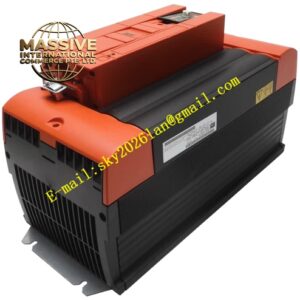
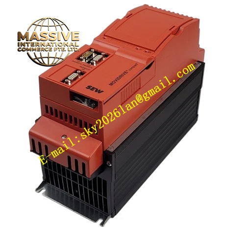
SEW MDX61B0014‑5A3‑4‑0T
Technical Specifications: Rated motor power: 1.5 kW Three‑phase input voltage: 380 VAC‑500 VAC, 50‑60 Hz Control modes: U/f open‑loop control, VFC flux control, CFC closed‑loop vector control, synchronous servo closed‑loop control Communication method: Binary terminal control, supports plug‑in fieldbus option cards Built‑in brake chopper for four‑quadrant operation Protection class: IP20 Ambient operating temperature: 0 ℃‑+45 ℃ Cooling method: Forced air cooling Independent 24 VDC control power supply, maintains parameter retention and bus communication under main circuit power loss
Functional Features: Vertical screw fastening installation inside closed electrical cabinet, IP20 protection takes effect only in cabinet environment. Complete hardware protection mechanisms cover overcurrent, overvoltage, undervoltage, overheating, earth fault, output short‑circuit and encoder signal failure. Realizes high‑precision closed‑loop drive for SEW asynchronous motors and synchronous servo motors. Equipped with multiple isolated digital inputs, digital outputs and one relay output, supports PTC motor winding temperature detection input. Completes automatic motor data identification and self‑tuning during commissioning, supports parameter backup and restoration. Embeds absolute positioning, relative positioning, electronic gearing, electronic cam and flying shear function modules. Integrated STO safety function meets functional safety requirements. Comprehensive fault memory stores fault codes, operating status and timestamp data. DC bus interconnection terminals implement regenerative energy sharing among multiple drives. Side expansion slots accept different encoder and fieldbus option cards. Supports DBG60B handheld operator panel and MOVITOOLS MotionStudio software for parameter configuration, real‑time status monitoring and fault diagnosisSEW-EURODR….
Application Scenarios: Packaging machine high‑dynamic servo positioning axis Labeling machine main servo drive Light‑and‑medium‑load automated assembly positioning axis Small‑format printing equipment register‑correction servo Light‑duty rotary indexing table control
Performance Parameters: Output frequency range: 0 Hz‑400 Hz Overload capacity: 150 % rated output current lasting 60 seconds Closed‑loop speed control accuracy reaches ±0.01 % Multi‑stage speed function, independently configurable acceleration ramp, deceleration ramp and S‑curve profile Torque limit setting and pure torque control mode available High‑speed encoder signal sampling circuit, compatible with incremental encoder and HIPERFACE absolute encoder Supports multi‑drive electronic synchronization and flying‑shear motion task
Material Composition: Cold‑rolled steel sheet housing processed with powder‑coating anti‑corrosion treatment Multi‑layer industrial grade printed circuit boards for power stage and control unit, IGBT power inverter modules, NTC temperature sensing elements Gold‑plated signal terminals, high‑conductivity thick copper power connection terminals Flame‑retardant plastic insulating support components, high‑voltage DC‑bus electrolytic capacitors Aluminum alloy metal heat sink assembly with built‑in cooling fan
Structural Characteristics: Modular vertical cabinet‑mount structure, rear panel reserves screw mounting holes. Front panel is fitted with tri‑color LED indicators for running state, fault alarm and fieldbus communication status. High‑current power terminals are arranged in upper area, low‑voltage signal terminals are placed in lower zone. Side slots for installing optional function cards. Physical separation layout between power cavity and signal cavity suppresses electromagnetic interference. Detachable plug‑gable terminal blocks simplify field wiring and maintenance work. DC‑bus interconnection terminals realize parallel connection of multiple drive units.
Working Principle: Three‑phase alternating current flows into main circuit terminals. Internal rectifier bridge converts AC power into stable DC‑bus voltage. IGBT inverter module converts direct current into continuously adjustable three‑phase alternating current for motor driving. Encoder transmits real‑time rotor speed and position feedback signals to main control board. CFC vector control algorithm calculates motor magnetic flux and output torque in real‑time, dynamically adjusts output voltage and frequency to achieve high‑precision closed‑loop speed and position regulation. Regenerative energy generated during motor deceleration is dissipated to external brake resistor through built‑in brake chopper. Once fault condition is detected, hardware protection circuit immediately cuts power output, triggers fault indicator and saves fault log data. Multiple connected inverters share regenerative braking energy through DC‑bus interconnection terminals.
Installation Requirements: Only vertical upright installation inside closed electrical cabinet, inverted and horizontal installation are strictly prohibited. Sufficient vertical clearance must be reserved above and below unit, cooling fan air inlet and outlet shall not be blocked. Power cables, motor cables, encoder cables and communication cables must run in separate cable ducts, all signal cables adopt shielded structure. Actual three‑phase input voltage matches nameplate rated specification. Cabinet internal environment keeps free from conductive dust, corrosive gas and condensation moisture. PE protective earth terminal must make firm connection with cabinet grounding busbar. Encoder wiring applies SEW dedicated shielded encoder cable. Metal shielding cover must be reinstalled after completing option‑card installation.
Precautions for Use: Wait minimum 10 minutes after power‑off to finish DC‑bus capacitor full discharge before opening housing for maintenance work. Verify three‑phase input voltage balance status before power‑on execution. Execute complete motor parameter identification procedure in commissioning phase. Do not connect parallel capacitor or surge absorber on inverter output side. Regularly remove dust accumulated on cooling fan and heat sink to prevent over‑temperature shutdown. Apply ESD anti‑static protection during option‑card plug‑in and replacement. External brake resistor must conform to drive rated parameter, short‑circuit of brake resistor terminals is forbidden. STO safety circuit wiring strictly complies with official safety operation manual.