Description
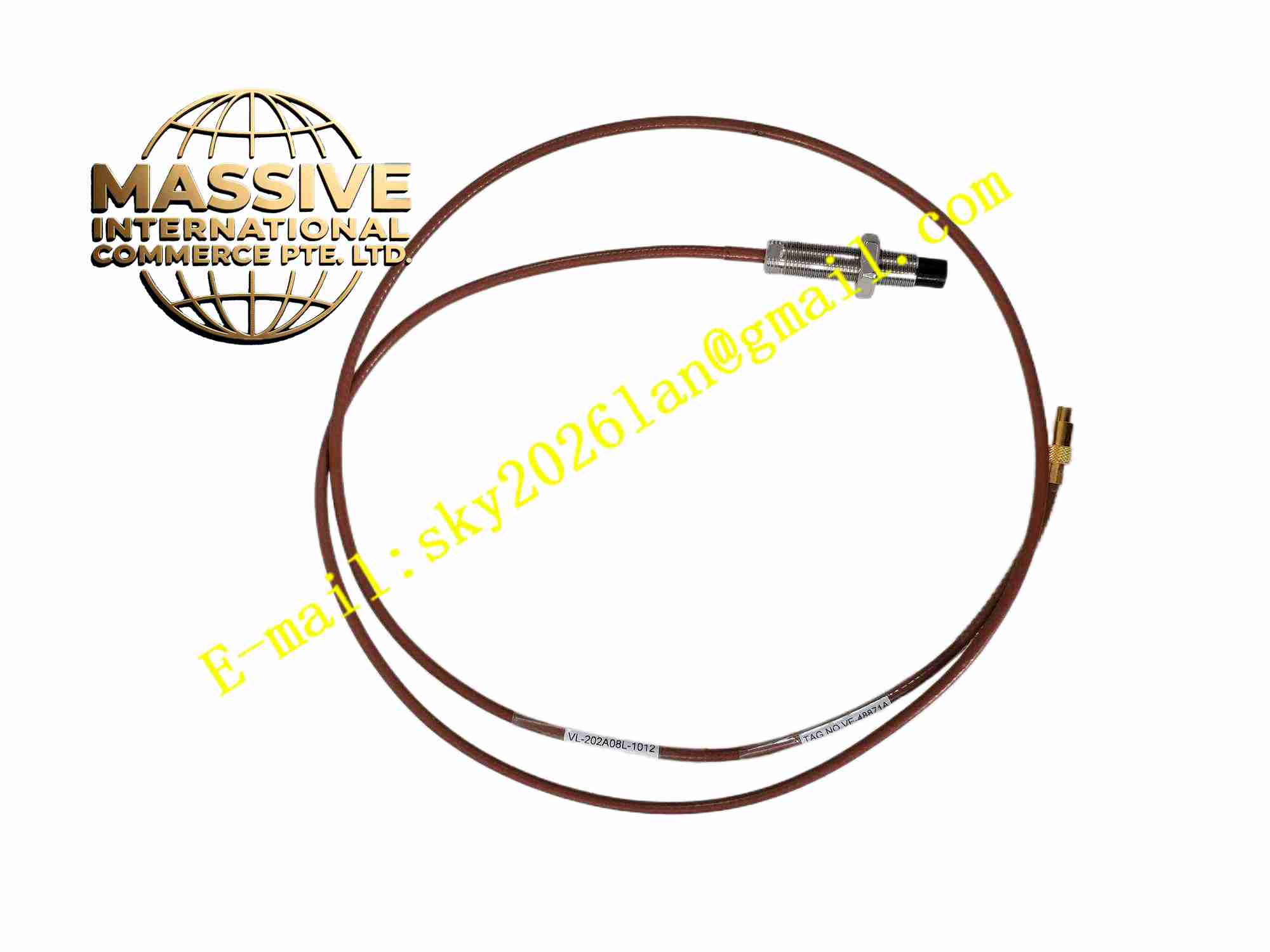
SHINKAWA VL-202A08L-1012
Technical Specifications: Model: VL-202A08L-1012 Probe tip diameter: 8mm Cable length: 10 meters Measurement principle: Eddy current non-contact measurement Target material: Ferromagnetic and non-ferromagnetic metal shaft Operating temperature: -20℃ ~ +180℃ at probe tip Output: High frequency coil signal to monitor unit Mounting: Threaded mounting into probe bracket Protection class: Hermetically sealed probe tip
Functional Features: Non-contact measurement of metal shaft surface distance. High temperature resistant probe tip suitable for turbine casing installation. Long 10-meter integrated cable for remote monitor cabinet connection. High linearity measurement within working gap range. Hermetically sealed probe tip against oil mist and steam. Matched with SHINKAWA VM-5 series monitor modules. Resist oil, steam and dust in turbomachinery casing environment.
Application Scenarios: Steam turbine shaft vibration measurement, gas turbine thrust displacement monitoring, centrifugal compressor shaft relative vibration, large generator shaft eccentricity measurement, turbomachinery TSI system proximity measurement.
Performance Parameters: High linearity in specified working gap range. High temperature endurance at probe tip installation position. Stable coil characteristic under oil mist environment. Low signal attenuation along 10m integrated cable.
Material Composition: High temperature resistant ceramic probe tip. Platinum alloy probe coil. Teflon insulated coaxial integrated cable. Stainless steel threaded mounting body. Hermetic metal sealing structure.
Structural Features: Cylindrical stainless steel probe body with external mounting thread. Front ceramic tip encapsulates internal coil. Integrated 10m coaxial cable connected to probe body. Cable outer sheath resistant to oil and high temperature. Connector end for connection to monitor extension cable.
Working Principle: High frequency excitation signal from monitor module passes through coaxial cable to probe internal coil. The coil creates alternating electromagnetic field at probe tip. Eddy current generates on metal shaft target surface. The eddy current field counteracts probe coil magnetic field. The coil impedance changes proportionally with gap distance between probe tip and shaft surface. The monitor module detects impedance variation and converts value to physical distance, vibration or thrust displacement.
Installation Requirements: Install probe into threaded bracket fixed on machine casing. Adjust initial gap between probe tip and shaft target surface according to calibration curve. Fix cable with cable clamps to avoid vibration induced cable fatigue. Route cable away from high temperature hot surface. Use matching extension cable from SHINKAWA for connection to monitor module.
Usage Notes: Avoid collision between probe tip and rotating shaft during commissioning. Check cable sheath for oil erosion and crack periodically. Do not cut or splice the integrated coaxial cable. Verify target shaft surface material meets probe specification. Carry out gap calibration before machine start-up.