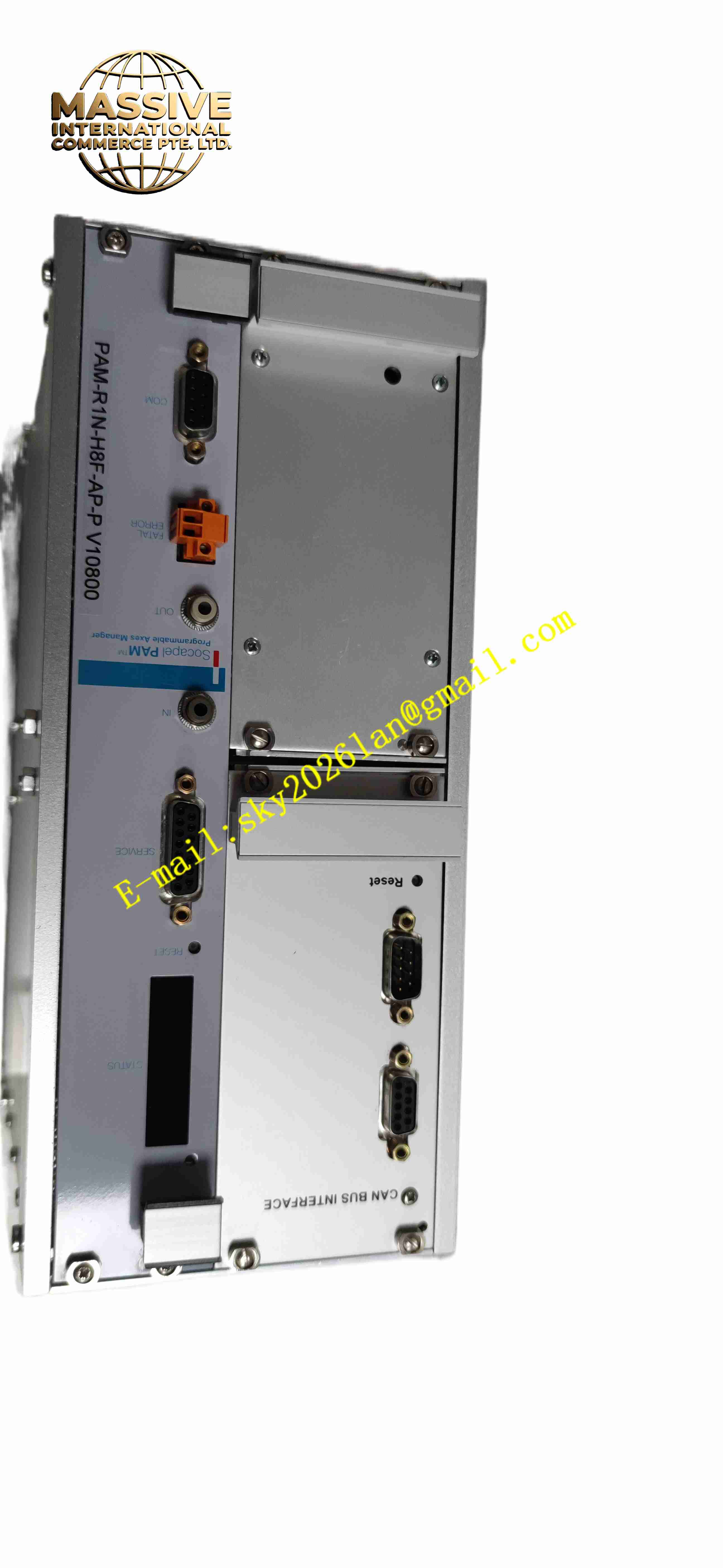
Description
Socapel H006.7538 PAM-R1N-H8F-AP-P V10800
Technical Specifications
- Product Type: Machinery safety relay module
- Power Supply: 24 V DC
- Safety Input: Dual channel safety contact input for emergency stop or safety gate
- Safety Output: Redundant force-guided safety relay contacts
- Contact Rating: 250 V AC, 6 A per contact
- Safety Category: EN ISO 13849-1 PL d, Category 3
- Diagnostic Functions: Cross wire fault detection, contact welding detection
- Protection Rating: IP20
- Operating Temperature: -10 °C to +55 °C
- Mounting: Standard 35 mm DIN rail mounting
- Response Time: < 25 ms
Functional Features
- Dual channel safety input circuit for emergency stop and safety guard door contact monitoring.
- Force-guided redundant safety relay contacts for safe de-energising of machine actuators.
- Cross fault detection identifies wiring short between two safety input channels.
- Contact welding detection monitors relay contact state to detect stuck closed fault.
- Manual or automatic reset mode selectable for safety interlock recovery.
- LED indicators show power status, safety input state and fault alarm.
- Reverse polarity protection for 24 V DC power supply.
- Compact DIN rail housing saves cabinet installation space.
- Continuous self-test runs during operation to verify internal safety relay integrity.
- EMC immunity for industrial cabinet environment with motor and drive noise.
Application Scenarios
- Packaging machine safety gate and emergency stop safety circuit
- Machine tool guard door safety interlock control
- Conveyor system emergency stop safety monitoring
- Automated assembly cell safety interlock system
- Material handling machinery safety contactor control
Material Composition
- Housing: Flame-retardant polycarbonate plastic enclosure
- Main PCB: FR4 printed circuit board with conformal coating
- Safety components: Force-guided safety relays
- Protection components: Surge suppression diodes and current limit resistors
- Terminal blocks: Tin-plated copper alloy screw terminals
- Isolation components: Optocoupler isolation chips for input channels
Structural Characteristics
- Slim single width DIN rail plastic housing.
- Front panel LED indicators for power, safety channel status and fault.
- Rear screw terminal blocks for safety input, power supply and safety output wiring.
- Internal dual redundant safety circuit architecture for safety category compliance.
- Force-guided relay mechanical linkage ensures contact positive separation under fault.
- Passive convection cooling without fan components.
Working Principle Dual safety contact signals from emergency stop or safety gate enter two independent input channels of PAM-R1N-H8F-AP-P V10800. The module continuously compares signal state of both channels. If channel mismatch, short circuit or contact welding is detected, internal safety relay de-energises immediately. Redundant force-guided contacts open to cut power to machine safety contactor. After safety fault removal, reset command restores safety output only when both safety channels return to normal state. LED indicators display fault condition for maintenance.
Installation Requirements
- Mount module on 35 mm DIN rail inside control cabinet.
- Use shielded twisted pair cable for safety input wiring of emergency stop and safety gate.
- Separate safety circuit wiring from high power motor cables.
- Complete protective earth connection to cabinet ground bar.
- Select manual or automatic reset mode according to machine safety requirement.
- Perform safety function test and fault simulation test after wiring completion.
- Verify force-guided contact wiring to safety contactor coil.
Usage Notes
- Use only force-guided safety contactors in downstream safety circuit.
- Do not bypass safety input channels for test operation.
- Keep cabinet dry and free of conductive dust and corrosive gas.
- Inspect terminal screw tightness periodically under vibration environment.
- Disconnect power before modifying safety wiring.
- Use anti-static wristband when handling spare module.
- Replace module immediately when permanent safety relay or diagnostic fault occurs.