Description
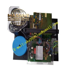
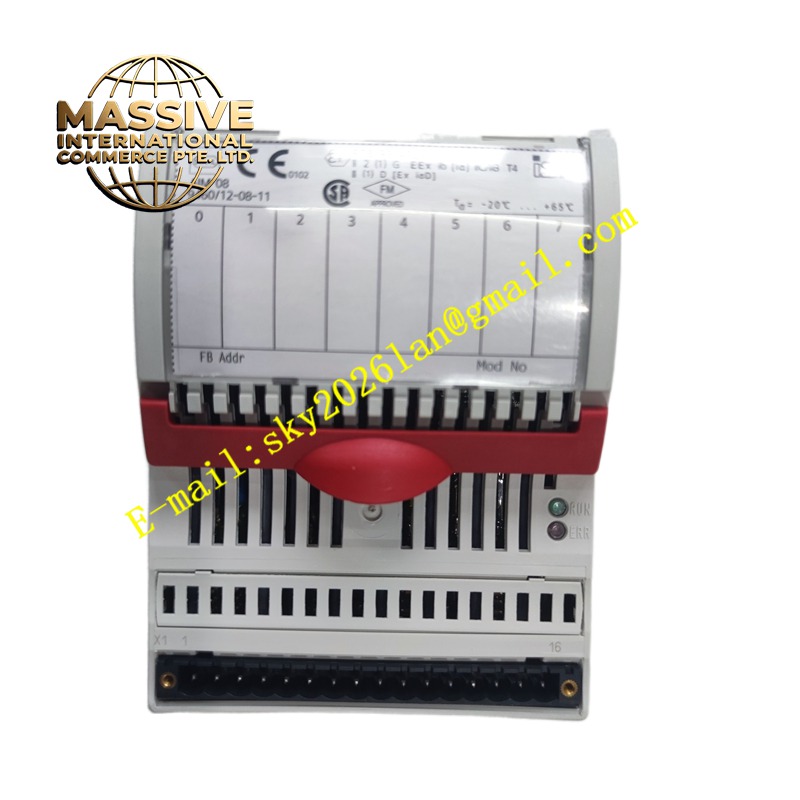
Stahl 946012-08-11
Technical Specifications Intrinsic safety approval for hazardous locations; galvanic isolation; multi-channel discrete signal support; energy limiting circuit for field side; 24V auxiliary power; DIN rail installation.
Functional Features Supplies limited safe energy to field intrinsically safe contact sensors and proximity switches. Transmits discrete switch status signals from hazardous area to control room I/O systems. Isolates ground potential difference between field and control cabinet. Provides protection against excessive energy entering the explosive atmosphere.
Application Scenarios Chemical hazardous area discrete signal monitoring, oil and gas field valve position feedback, dust explosion risk zone limit switch signal acquisition.
Performance Parameters Fast digital signal response; stable isolation withstand voltage; strict energy limitation; low signal state transition delay.
Material Composition Outer casing is flame-retardant thermoplastic; internal isolation and protection components are explosion-proof qualified; circuit substrate is FR-4 flame-retardant printed circuit board; terminal hardware is corrosion-resistant nickel-plated alloy.
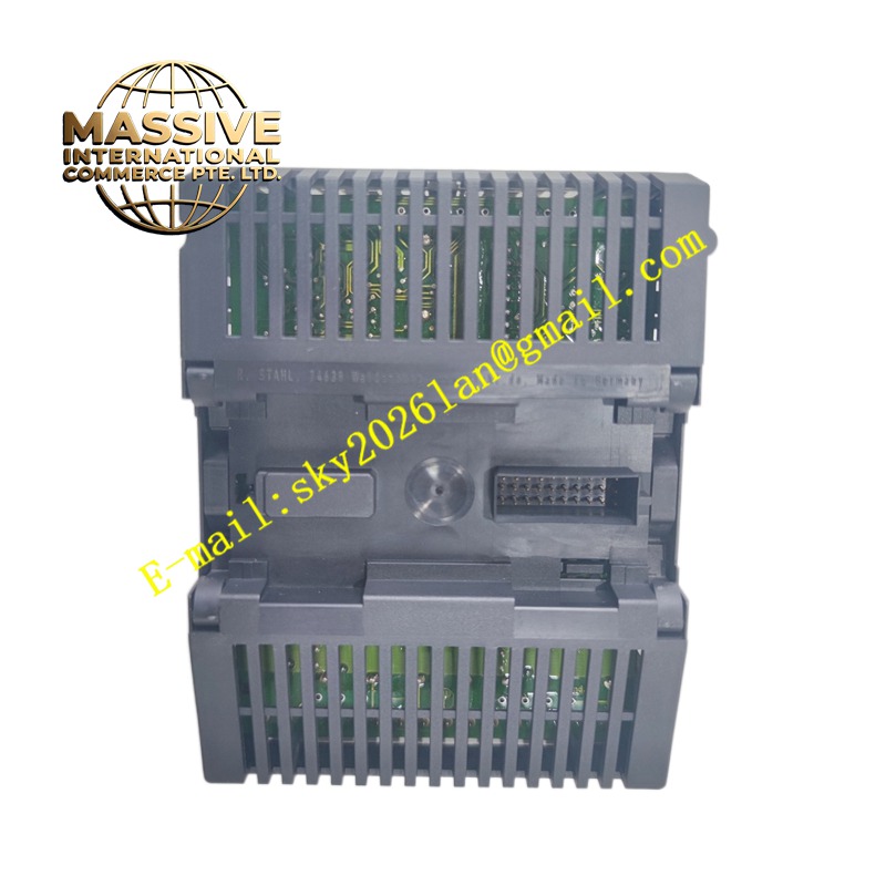
Structural Characteristics Compact DIN rail housing; independent terminal partitions for hazardous field wiring and safe control wiring; printed terminal function marking on the housing surface; rear DIN rail fastening clip.
Working Principle The energy limiting circuit restricts voltage and current output to field intrinsically safe sensors. Digital switch state signals are coupled through the isolation unit to the safe side control circuit. The isolation barrier eliminates ground loop interference and prevents dangerous energy leakage to the hazardous zone.
Installation Requirements Mount the isolator in non-hazardous control cabinets. Keep hazardous zone wiring physically separated from safe zone cables. Complete grounding according to local intrinsic safety installation codes. Match the energy parameters with the connected field sensors.
Precautions for Use Do not use this product beyond the certified hazardous area classification. Do not connect non-intrinsically safe loads to the field side terminals. Inspect terminal tightness periodically in corrosive environments.