Description
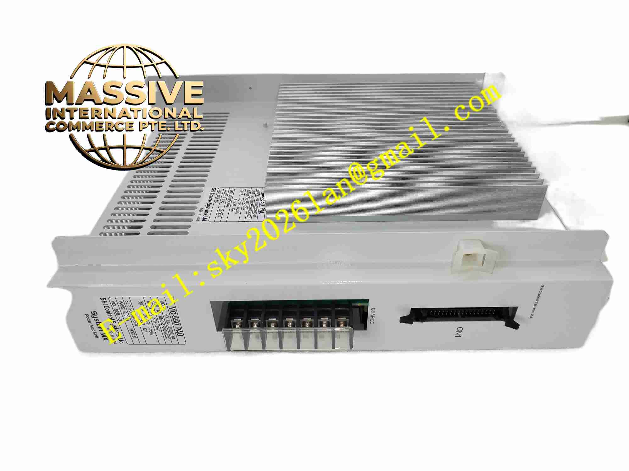
Sumitomo UMC552000-01
Technical Specifications AC single/three phase input; Position and speed control mode; Incremental encoder feedback interface; Built-in multi-level protection functions; Digital input/output for enable, alarm and limit signal; Serial communication interface for parameter setting; Operating temperature 0°C ~ +50°C; PWM power output.
Functional Features Suppression function for mechanical resonance reduces vibration at low speed; Simple parameter setup via software or panel; Alarm code display for rapid fault diagnosis; Electronic gear ratio configuration; Enable and emergency stop digital input interface; Smooth acceleration and deceleration profile; Parameter saving inside non-volatile memory.
Application Scenarios Small automated assembly machines; Labeling equipment; Desktop test machines; Light-duty material feeding mechanism; Small conveyor positioning control; Miniature cutting and marking equipment.
Performance Parameters Low speed operation smoothness is excellent; Positioning repeatability is high; Resonance suppression effectively reduces mechanical oscillation; Parameter storage remains intact after power loss; Alarm detection sensitivity is stable.
Material Composition Aluminum alloy heat sink housing; Power semiconductor devices; Multi-layer glass fiber PCB; Encoder signal receiver; Current sampling circuit; Screw terminal connectors; LED indicator lights.
Structural Features Compact vertical mounting structure; Aluminum heat sink with cooling fins; Front panel LED indicators for power, run and fault; Separate terminal blocks for power, motor, encoder and digital signals; Control circuit and power circuit physical isolation inside unit.
Working Principle Motion command signal enters the amplifier control board. Encoder feeds back motor actual position and speed signal. Onboard processor calculates deviation between command and feedback, generates PWM drive signal for power circuit. Power circuit outputs adjustable three-phase power to servo motor. Resonance suppression algorithm filters vibration frequency component to smooth motor operation. Once fault condition detected, power output cuts off and alarm indicator activates.
Installation Requirements Install on flat metal surface for heat dissipation; Keep clearance for air flow; Shielded twisted pair cable used for encoder wiring; Protective ground connection is mandatory; Separate signal cable and power cable routing.
Precautions for Use Wait for capacitor discharge before opening cover after power cut; Verify motor model matches amplifier rating; Do not overload continuously; Regularly remove dust accumulated on heat sink; Emergency stop wiring must use hard-wire safety circuit.