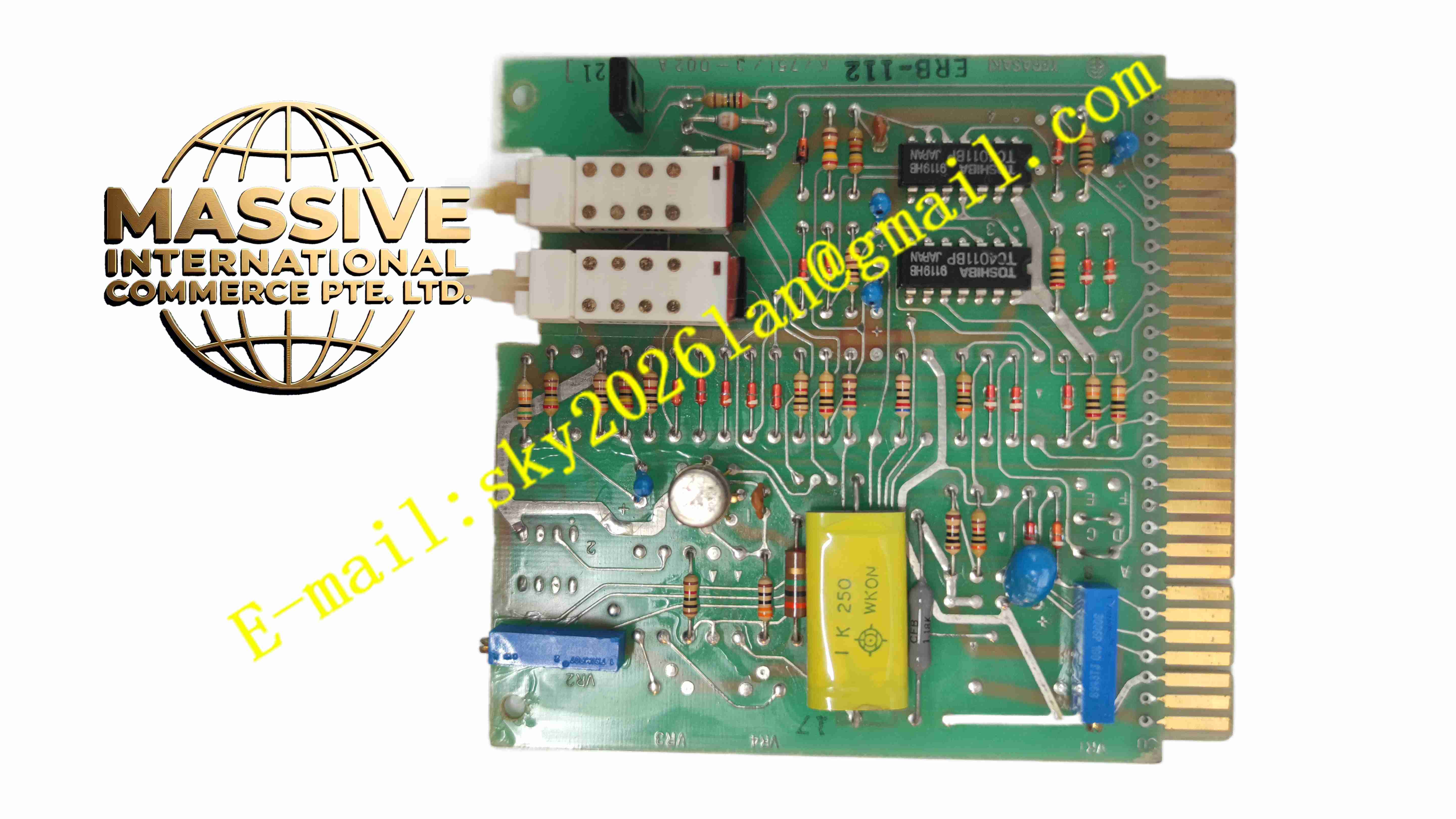
Description
TERASAKI ERB-112
Technical Specifications
- Brand: TERASAKI
- Model: ERB-112
- Product Type: Electronic relay module
- Application Area: Industrial control, marine electrical systems, power distribution panels
- Control Input: Low-voltage control signal input, subject to nameplate rating
- Output Function: Relay output for switching, alarm, interlock, or protection signals
- Mounting Type: Panel or rack-mounted module, depending on system configuration
- Communication: May interface with TERASAKI protection relays or control units
- Environmental Suitability: Designed for indoor industrial and marine control environments
Functional Features
- Reliable Switching: Provides stable relay output for control and protection functions.
- Compact Module Design: Fits into standardized TERASAKI control or protection assemblies.
- Protection Support: Can be used in motor protection, breaker control, and alarm circuits.
- Signal Isolation: Helps separate control logic from high-power circuits.
- Easy Integration: Designed to work with TERASAKI protection relays and switchgear systems.
- Diagnostic Support: Supports status indication and fault signal feedback where configured.
- Industrial Durability: Built for continuous operation in demanding electrical environments.
Application Scenarios
- Marine electrical switchboards
- Industrial motor control centers
- Power distribution protection panels
- Generator control systems
- Alarm and interlock circuits
- Auxiliary control circuits in substations and plants
Performance Parameters
- Response Behavior: Fast relay response for protection and control applications.
- Output Stability: Maintains consistent switching under rated operating conditions.
- Electrical Isolation: Provides isolation between control signals and load circuits.
- Operating Life: Designed for long service life in industrial and marine applications.
- Environmental Resistance: Suitable for environments with moderate vibration and temperature variation.
Material Composition
- Housing: Flame-retardant engineering plastic for insulation and mechanical protection.
- PCB: Industrial-grade printed circuit board with relay driver and signal circuits.
- Relay Elements: Electromechanical or solid-state relay components for output switching.
- Terminals: Screw or plug-in terminals for secure wiring connections.
- Protection Components: Fuses, varistors, or transient suppression devices for electrical protection.
- Indicators: LED indicators for power, output status, or fault conditions.
Structural Features
- Modular Form Factor: Designed for integration into TERASAKI control or protection racks.
- Front or Side Terminals: Allows convenient wiring during installation and maintenance.
- Status Indication: Provides visual feedback for operating and fault conditions.
- Compact Layout: Saves space inside electrical control panels.
- Robust Enclosure: Protects internal electronics from dust, moisture, and mechanical stress.
- Serviceable Design: Supports replacement without disturbing the entire control system.
Working Principle
The ERB-112 receives control signals from a protection relay, PLC, or manual control circuit. When the input condition is satisfied, the internal relay changes its output state to energize or de-energize connected devices. The module monitors input signals and output status, providing feedback to the control system. If a fault or abnormal condition occurs, the relay can trigger an alarm, trip signal, or interlock action to protect downstream equipment.
Installation Requirements
- Verify the correct model and system compatibility before installation.
- Install in a dry, clean, and well-ventilated control panel.
- Ensure the supply voltage matches the module nameplate rating.
- Use proper wiring methods for control and load circuits.
- Keep control wiring separated from high-power cables.
- Tighten terminals to the recommended torque.
- Confirm system configuration and protection settings before commissioning.
Precautions for Use
- Do not exceed the rated input voltage or output load capacity.
- Do not install the module in wet or corrosive environments.
- Verify wiring polarity and terminal assignments before energizing.
- Do not bypass protection or interlock functions.
- Perform regular inspection of terminals, indicators, and mounting condition.
- Replace failed modules with the same model and version.
- Only qualified electrical personnel should install or maintain the device.
- Refer to the official TERASAKI manual for exact electrical ratings.