Description
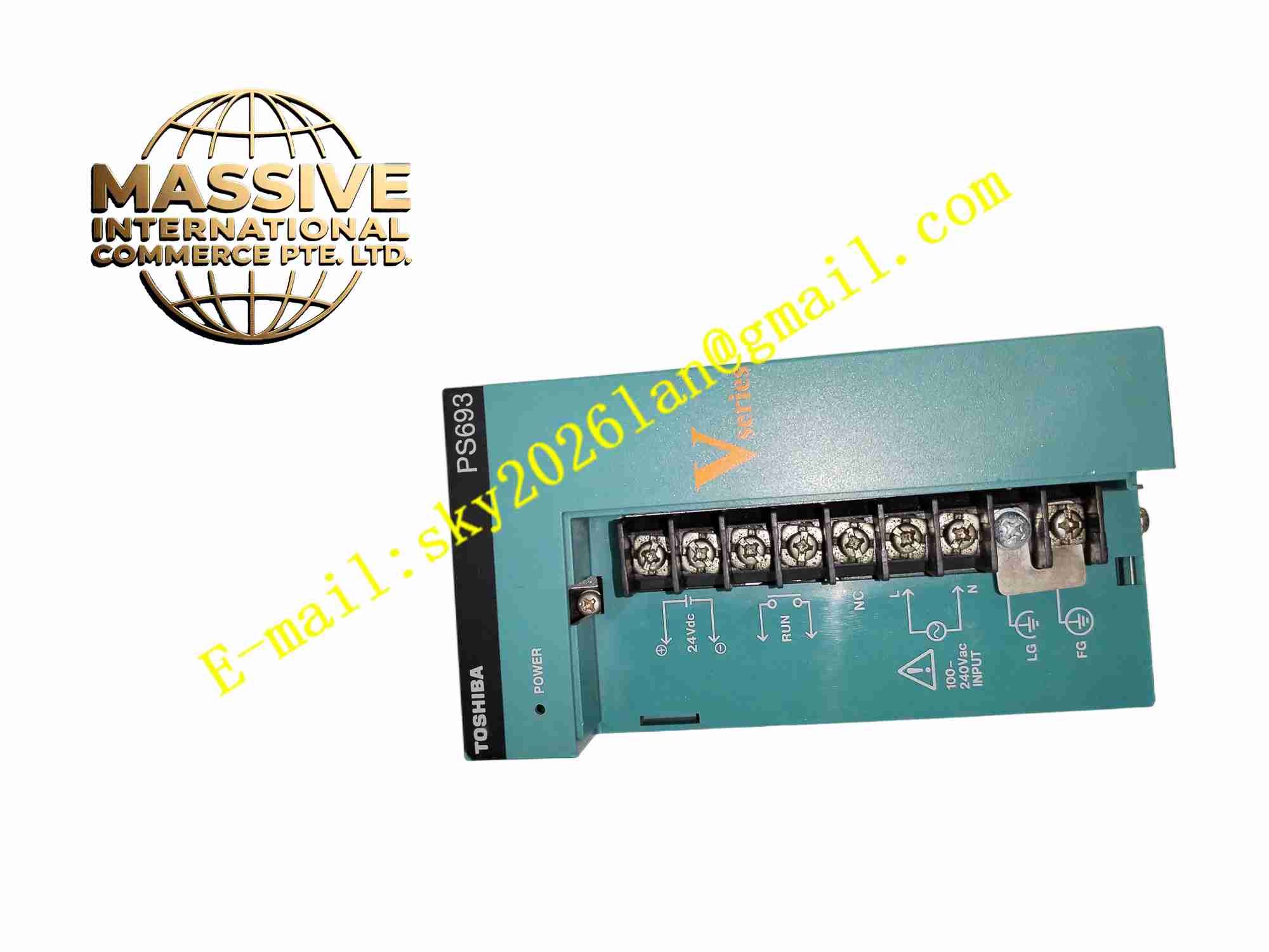
Toshiba PS693 Industrial PLC Power Supply Module
Technical Specifications Model: PS693 Input Voltage: 100 ~ 240VAC wide range AC input, 50/60Hz DC Output Channels: 5VDC / 7A, 3.3VDC /1A, 24VDC /0.8A Mounting Method: Plug-in module mounting on PLC base rack Operating Temperature: 0℃ ~ +60℃ Storage Temperature: -20℃ ~ +75℃ Relative Humidity: 10% ~ 90% non-condensing Protection Function: Overvoltage protection, overcurrent protection, overheat protection Backplane Bus: Toshiba G2 I/O bus Module Status Indicator: Power OK LED indicator
Functional Features Wide range AC input adapts to fluctuation of industrial factory AC power grid. Multi-channel regulated DC output supplies power for PLC controller core, logic circuit and field I/O signal circuit. Built-in multiple protection circuits trigger power shutdown automatically under overvoltage, overcurrent and overheat fault. Power OK LED indicator displays normal power output status. Plug-in hot-swap free module design, install and remove on PLC base rack. Stable output voltage under load variation and input voltage fluctuation. Low ripple DC output reduces interference to PLC control logic and communication signal. Supports continuous long-time operation for industrial automation control cabinet.
Application Scenarios Factory assembly line PLC control cabinet, chemical industry DCS auxiliary control rack, water treatment automatic control system, building automation controller, packaging machine and textile machine PLC control system.
Performance Parameters Output voltage ripple maintains low value under full rated load. Protection circuit responds rapidly when overvoltage, overcurrent or overheat fault occurs. Output voltage keeps stable within specified tolerance when AC input fluctuates between 100VAC to 240VAC. Power module maintains stable output performance during long-time continuous operation. Protection circuit automatically recovers after fault condition is removed and power reset. Backplane bus power transmission keeps stable communication between rack modules.
Material Composition Module housing: Black flame-retardant engineering plastic. Main PCB: FR4 multi-layer industrial printed circuit board with conformal coating. Core electronic components: AC-DC switching power chip, high frequency transformer, rectifier diode, output filter capacitor, overvoltage/overcurrent protection IC, optocoupler isolation component. Connector: Gold-plated backplane edge connector for PLC base rack connection. LED indicator: Power status light emitting diode. Fasteners: Plastic buckle and metal fixing clips.
Structural Features Rectangular plug-in module structure designed for installation on Toshiba PLC base rack. Front panel equipped with power OK LED indicator. Gold-plated edge connector on module rear side inserts into base rack backplane socket. Internal layout separates AC input high voltage circuit and low voltage DC output circuit with isolation barrier. Heat dissipation realized by natural convection through module casing ventilation holes. Module side equipped with positioning buckle for accurate alignment with rack slot.
Working Principle AC input voltage enters module through backplane connector. EMI filter circuit suppresses grid interference. High-frequency switching circuit converts AC voltage into isolated multi-channel DC voltage. Rectifier and filter circuit smooth DC output ripple. Voltage feedback circuit continuously monitors output voltage and adjusts switching duty cycle to keep stable output value. Overvoltage, overcurrent and overheat protection circuit monitors operating status in real time. Once fault condition exceeds threshold, protection circuit shuts down switching power stage immediately to protect power module and other PLC modules on rack. Power OK LED lights up when all DC output channels work normally.
Installation Requirements Power off entire PLC rack before installation and removal of PS693 module. Align module with empty slot on Toshiba PLC base rack, push module inward until backplane connector fully inserts into rack socket and positioning buckle locks. Check module front panel LED status after system power on. Reserve ventilation space around module on rack, avoid heat accumulation. Connect AC power wiring to base rack power terminal according to wiring diagram. Check all output voltage value with multimeter in commissioning phase.
Usage Precautions Module must only be used with matched Toshiba V-series / nv series PLC base rack, cannot work with other brand PLC racks. Cut off rack main AC power before plugging or unplugging module. Do not exceed rated output current of each DC channel. Avoid installation environment with condensation, corrosive gas and conductive dust. Regularly check ventilation holes for dust accumulation, clean dust periodically. Do not open plastic module housing without professional authorization, internal high voltage circuit exists. Module must be replaced if repeated power protection shutdown occurs.