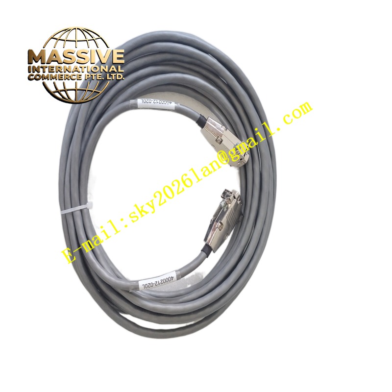
Description
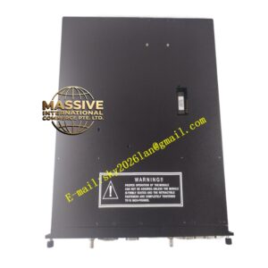
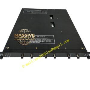
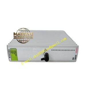
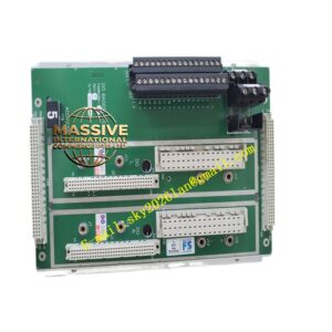
Triconex 4000212-020L
Technical Specifications:
- Brand: Triconex (part of Schneider Electric / formerly Invensys)
- Model: 4000212-020L
- Product Type: Field Termination Assembly (FTA) for Tricon TMR I/O
- HS Code: 8537.10 (Boards, panels, consoles for electric control, ≤1000 V)
- Power Requirements: Passive termination; no external power typically required
- Dimensions & Weight: Standard termination board form factor; installed weight approximately 1.0 kg
- Operating Temperature: 0 to 60 °C (typical industrial control cabinet environment)
- Signal Input/Output Types: Field screw/clamp terminals for discrete or analog channels, as defined by the paired Triconex I/O module
- Communication Interfaces: System cable header connector to Triconex I/O card; no independent network ports
- Installation Method: DIN-rail or panel mounting inside a grounded control cabinet
- Origin: Designed and manufactured to Triconex specifications
Functional Features:
- Structured channel labeling with channel IDs and terminal markings that mirror the paired I/O card, minimizing wiring errors and rework
- Robust screw/clamp terminals providing secure connections for discrete or analog signals, helping maintain signal integrity in electrically noisy industrial cabinets
- Integrated shield management with dedicated grounding points and clear routing paths for cable shields, reducing electromagnetic interference on low-level analog signals
- Cabinet-friendly footprint that fits comfortably on standard DIN rail or panel backplates, easing retrofits and system expansions
- Serviceable design with straightforward access to terminals and cable headers, making loop checks, troubleshooting, and maintenance faster and more efficient
- Passive operation requiring no external power supply, reducing system complexity and potential failure points
- Designed for direct compatibility with Triconex TMR I/O modules, ensuring seamless integration into the safety system architecture
Application Scenarios:
- Oil and Gas: Emergency Shutdown Systems (ESD), High-Integrity Pressure Protection Systems (HIPPS), Burner Management Systems (BMS), and compressor protection systems
- Chemicals and Petrochemicals: Process shutdown systems, safety interlocks, and critical process monitoring
- Power Generation: Boiler management systems, burner management, turbine auxiliary controls, and generator protection
- Pharmaceuticals and Specialty Manufacturing: Safety interlocks, utility monitoring, and batch process safety systems
- Pulp and Paper: Machine safety systems and critical process interlocks
- Marine and Offshore: Platform safety systems and emergency shutdown controls
- Any industrial facility deploying Triconex Tricon TMR safety PLCs where reliable field wiring is critical
Performance Parameters:
- Designed for continuous operation in industrial control cabinet environments (0 to 60 °C)
- Signal integrity maintained through robust terminal design and shield management
- Channel mapping accuracy ensures one-to-one correspondence with paired I/O module channels
- Mechanical durability supports repeated maintenance cycles and terminal connections
- Passive design eliminates power-related failure modes
- Compatible with the full range of discrete and analog signal types supported by the paired Triconex I/O module
Material Composition:
- High-quality printed circuit board (PCB) substrate with industrial-grade copper traces
- Robust screw/clamp terminal blocks made from thermoplastic or thermoset materials rated for industrial environments
- Metal mounting hardware (stainless steel or zinc-plated steel) for DIN rail or panel attachment
- Shield grounding components made from conductive metals (brass or steel)
- Connector header made from high-temperature thermoplastic with gold-plated or tin-plated contacts
- Conformal coating or solder mask applied to PCB for environmental protection
Structural Features:
- Compact rectangular PCB form factor optimized for control cabinet mounting
- Clearly labeled terminal blocks with channel identification matching the I/O card layout
- Dedicated shield termination points with clear routing guides for cable shields
- Robust system cable header connector for mating with the Triconex I/O module ribbon cable
- Mounting holes or DIN rail clips for secure installation
- Silkscreen labeling on PCB for terminal identification and orientation guidance
- Adequate creepage and clearance distances between terminals for safety compliance
- Serviceable layout allowing easy access to all terminals without removing adjacent equipment
Working Principle:
The Triconex 4000212-020L operates as a passive signal interface between field instruments and the Triconex TMR I/O processor modules. Field wiring from sensors, switches, transmitters, and actuators terminates at the screw/clamp terminals on the FTA. The FTA routes these signals through internal PCB traces to a multi-pin cable header connector, which mates with a ribbon cable leading to the corresponding Triconex I/O module.
For discrete signals, the FTA provides direct pass-through connectivity with appropriate terminal arrangements. For analog signals, the FTA includes shield grounding provisions to minimize noise pickup on sensitive low-level signals. The structured channel labeling ensures that each field wire connects to the correct terminal corresponding to the appropriate channel on the I/O module, maintaining the integrity of the TMR architecture where three independent signal paths are processed for fault tolerance.
The passive nature of the FTA means it introduces no active electronics into the signal path, eliminating a potential point of failure in the safety system. The robust terminal design and shield management features ensure that signal quality is maintained from the field instrument to the I/O module, which is critical for the accurate operation of safety-rated control functions.
Installation Requirements:
- Mount the FTA on a standard DIN rail or panel backplate inside a grounded control cabinet
- Ensure the control cabinet environment meets the specified operating temperature range (0 to 60 °C)
- Connect the system cable header to the corresponding Triconex I/O module using the specified ribbon cable
- Terminate field wiring at the appropriate screw/clamp terminals following the channel labeling
- Connect cable shields to the designated shield grounding points on the FTA
- Ensure all terminal connections are properly torqued to specification
- Verify correct orientation and seating of the ribbon cable connector
- Perform loop checks after installation to verify signal continuity and correct channel mapping
- Follow Triconex official installation manual and wiring diagrams for the specific I/O module configuration
- Ensure the control cabinet is properly grounded per industrial electrical standards
Usage Precautions:
- Verify the FTA model number matches the requirements of the paired Triconex I/O module
- Do not exceed the specified operating temperature range
- Ensure all field wiring connections are secure and properly torqued
- Connect cable shields to the designated grounding points to minimize interference
- Do not modify the FTA or its internal circuitry
- Handle the FTA with care to avoid damage to the PCB or connector pins
- Perform regular visual inspections for signs of corrosion, loose terminals, or physical damage
- Keep the FTA clean and free from dust, moisture, and conductive contaminants
- Use only genuine Triconex replacement parts and accessories
- Follow proper lockout/tagout procedures when performing maintenance on connected equipment
- Document all wiring connections and maintain updated as-built drawings
- Contact Triconex technical support for application-specific guidance
- Ensure personnel are trained on Triconex safety system architecture and maintenance procedures