Description
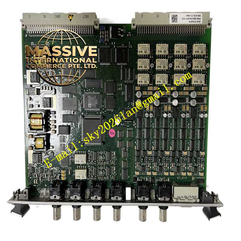
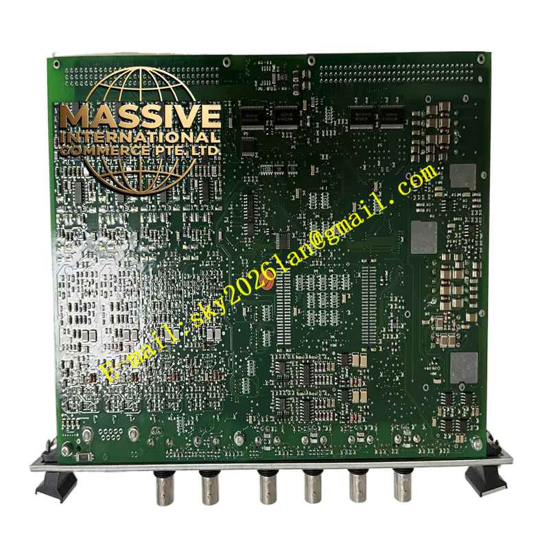
Vibro-Meter 200-510-071-113 / 200-510-111-034
Technical Specifications:
- Brand: Vibro-Meter
- Model: VM600MPC4
- Associated Part Numbers: 200-510-071-113, 200-510-111-034
- Product Type: Machinery Protection and Condition Monitoring Module
- System Platform: VM600
Functional Features:
- Multi-Channel Monitoring: Simultaneously monitors vibration, displacement, and speed parameters across multiple channels.
- Advanced Diagnostics: Provides real-time spectral analysis, waveform capture, and trend monitoring for predictive maintenance.
- Safety Compliance: Meets stringent API 670 and SIL 3 safety standards for automated machinery shutdown.
- Hot-Swappable Design: Allows for module replacement without powering down the entire VM600 rack.
Application Scenarios:
Extensively utilized in gas turbines, steam turbines, compressors, pumps, and industrial generators in oil & gas, power generation, and petrochemical industries.
Performance Parameters:
- Response Time: Ultra-fast processing for immediate alarm and trip generation.
- Signal Accuracy: High-resolution analog-to-digital conversion for precise vibration measurement.
Material Composition:
Industrial-grade printed circuit boards with protective conformal coatings and high-reliability electronic components.
Structural Characteristics:
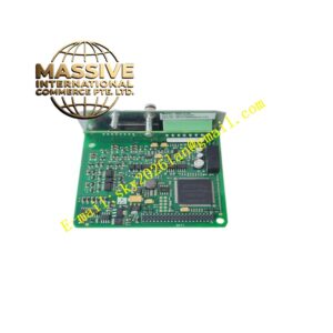
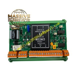
Compact, modular form factor designed for standard VM600 rack mounting. Features front-panel LED indicators and rear high-density connectors.
Working Principle:
Acquires raw sensor signals (proximity probes, accelerometers), processes the data using embedded DSP algorithms, and outputs alarm/trip relays and digital communication data to the control system.
Installation Requirements:
Insert into an available VM600 rack slot and secure with front-panel fasteners. Connect sensor cables and communication links according to the wiring diagram.
Usage Precautions:
Ensure proper grounding of the VM600 rack to prevent electromagnetic interference. Verify DIP switch settings match the system configuration before powering on.