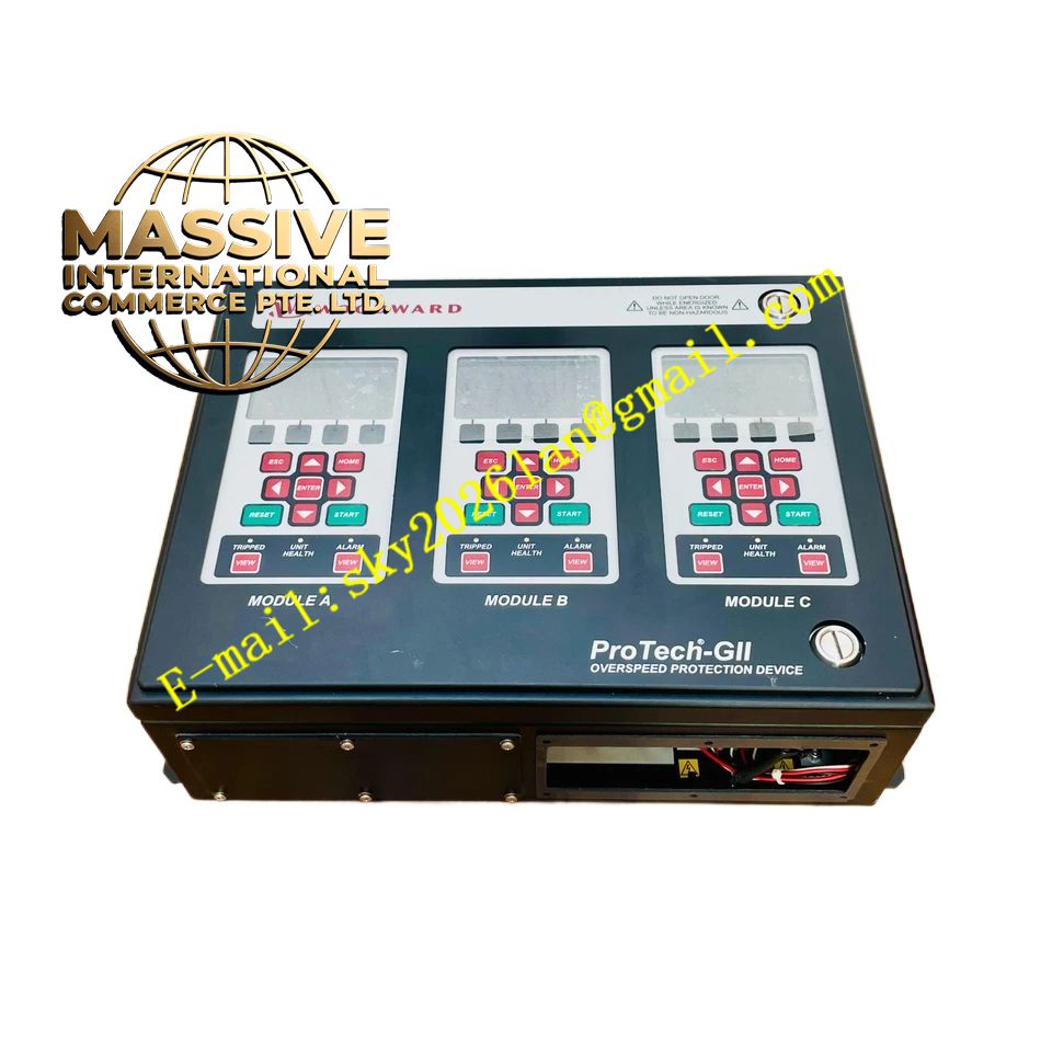
Description
Woodward PROTECH-GII
Technical Specifications
- Safety Certification: Certified for use in applications up to SIL3 according to IEC 61508.
- Redundancy: Triple Modular Redundant (TMR) architecture consisting of three independent modules (A, B, C).
- Voting Logic: Supports 2-out-of-3 (2oo3) voted architecture or three independent non-voted trip relay outputs.
- Response Time: System response time of 12 milliseconds.
- Speed Range: Applicable for speeds ranging from 0.5 to 32,000 RPM.
Functional Features
- Acceleration Detection: Derives acceleration from speed signals to detect and trip on high over-acceleration events.
- MPU Wire Break Detection: Verifies magnetic pickup connections before turbine start and monitors functionality during run.
- Hot Replacement: Allows operators to replace a single module while the turbine is online and operating normally.
- Auto-Test Program: Periodically executes internal overspeed tests using a built-in frequency generator.
- Communication: Features Modbus communication and 4-20 mA analog speed readouts for DCS integration.
Application Scenarios
Extensively applied in energy, manufacturing, oil and gas, and utility sectors to protect steam turbines, gas turbines, water turbines, and reciprocating engines.
Performance Parameters
- Product Life: 20 years when proper installation, maintenance, and environmental limitations are observed.
- Safe Failure Fraction (SFF): > 90%.
- Diagnostic Coverage (DC): > 90%.
Material Composition
Features specialized conformal coating materials providing excellent long-term protection against H2S and SO2 gases, meeting IEC 721-3-3 1994 environmental class 3C2.
Structural Characteristics
Panel or backplane-mounted design featuring a plug-and-operate structure. Each module includes a front panel interface with a display, keypad, and status LEDs.
Working Principle
The system monitors speed via active or passive magnetic pickups. The three modules share data via a safety-certified CAN network. If the voted speed or acceleration exceeds the programmed setpoint, the system de-energizes or energizes the trip relays to actuate the turbine’s shutdown valves.
Installation Requirements
Field wiring must use stranded copper wire sized between 1.5 and 6 mm² for power and 0.3 to 4 mm² for I/O. Wire ends must not be tinned or soldered to prevent cold flow over time.
Precautions for Use
Never disconnect wiring while the circuit is live in hazardous areas. Utilize the Test Level and Config Level passwords to prevent unauthorized parameter changes, adhering to NERC cyber security requirements.