Description
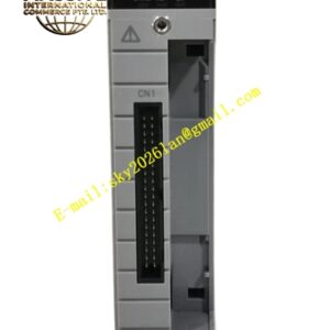
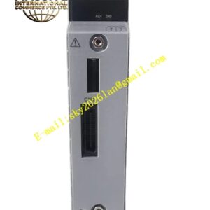
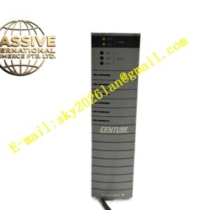
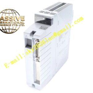
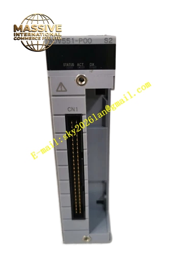
YOKOGAWA ADV551‑P00
Technical Specifications: Total output channel quantity: 32 channels; output type: sink‑type transistor output; rated load voltage: 24 VDC; maximum load current per channel: 100 mA; group‑wise galvanic isolation; response time ≤40 ms; P00 variant supports pulse‑width proportional output function; power consumption: max 700 mA at 5 VDC backplane supply; operating temperature: 0 °C‑60 °C; storage temperature:‑20 °C‑70 °C; relative humidity: 10‑90 %RH non‑condensing; CENTUM‑VP FIO rack‑slot mounting; front‑panel LED indicators for module run status and channel fault alarms; weight: 0.30 kg; supports open‑load detection for field output loops.
Functional Features: Thirty‑two‑channel sink‑type digital output for field discrete actuators; P00 hardware variant provides pulse‑width proportional output capability for special control applications; group‑wise galvanic isolation suppresses ground‑loop interference from field equipment; per‑channel open‑load detection identifies broken field wiring or actuator disconnection; hardware self‑diagnosis detects internal module hardware failure and backplane communication fault; front‑panel LED array offers visual module‑status and fault indication; supports dual‑redundant module configuration for high‑availability control loops; receives digital output commands from CENTUM‑VP CPU via rack backplane bus.
Application Scenarios: Petrochemical plant solenoid‑valve on‑off control loops; chemical‑process plant motor‑start‑stop discrete control; refinery field alarm‑lamp driving; oil‑gas processing plant discrete actuator control points; CENTUM‑VP DCS system maintenance and spare‑part replacement projects.
Performance Parameters: Output switching timing accuracy satisfies CENTUM‑VP DCS process‑control requirements; group‑wise isolation dielectric strength complies with industrial process‑instrument standards; vibration and shock resistance meets cabinet‑mount control‑hardware specifications; supports continuous 24‑7 operation inside non‑condensing industrial control cabinets.
Material Composition: Orange V0 flame‑retardant engineering‑plastic rack‑module housing; FR‑4 multi‑layer glass‑fiber printed circuit board; transistor output drive semiconductors; group‑wise galvanic isolation components; gold‑plated backplane edge‑connector contacts; multi‑color SMD LED status indicators; metal mechanical locking latches.
Structural Features: Standard CENTUM‑VP FIO rack‑slot mechanical profile; rear‑side gold‑plated edge‑connector mates with rack backplane bus; front‑panel equipped with RUN and fault‑status LED indicators; side metal latches secure module firmly into FIO rack I/O slot; all field‑actuator wiring connects externally through matched terminal‑block assembly.
Working Principle: CENTUM‑VP control‑station CPU transmits digital output commands to ADV551‑P00 module through rack backplane bus. Internal logic circuit processes received command values. For regular on‑off output mode, transistor drive circuits turn on or off sink‑type output channels to switch 24 VDC field‑loop current. For pulse‑width proportional mode, internal timing circuit generates adjustable‑duty‑cycle pulse output signals. Group‑wise isolation circuits separate module internal digital logic domain from field‑side 24 VDC loops. Onboard diagnostic circuits monitor output‑loop load condition continuously, detect open‑load faults and internal hardware anomalies, activate corresponding front‑panel LED status indicators.
Installation Requirements: Insert ADV551‑P00 into valid I/O slot of CENTUM‑VP FIO main rack or expansion rack; engage side‑panel mechanical latches for firm rack‑slot fixation; deploy matched terminal‑block assemblies for all field 24 VDC loop wiring; use shielded twisted‑pair cables for field discrete‑signal wiring; separate field‑output cables from high‑power motor and inverter power cables; implement reliable protective grounding for control cabinet and rack assembly.
Usage Notes: Follow official hot‑swap operation procedures for module replacement under powered‑on rack status; configure output mode and fault‑safe state inside CENTUM‑VP engineering software during commissioning; do not exceed per‑channel maximum 100 mA load‑current rating; avoid deployment in environments with corrosive gas, liquid splash or condensation; inspect terminal‑block screw tightening torque during periodic maintenance cycles.