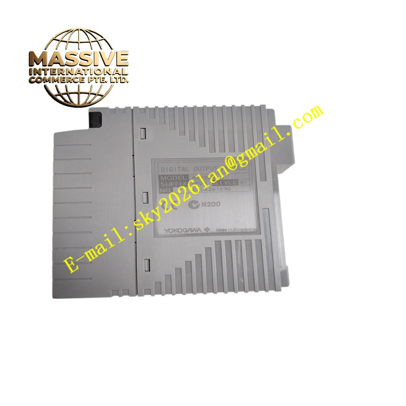
Description
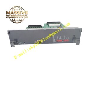
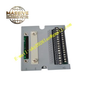
Yokogawa ADV551-P60
Technical Specifications 16 isolated analog output channels; output signal range 4 to 20mA; output resolution 16 bits; basic output accuracy ±0.1% full scale; load resistance maximum 750Ω at 20mA; isolation withstand voltage 1500V AC between field circuit and system backplane; HART 5/6/7 protocol support; power consumption 600mA at 24V DC; operating temperature -20°C to +70°C; IP20 protection class.
Functional Features Receives digital setpoint values from the CENTUM VP controller and converts the values into stable 4-20mA current outputs. Supports HART digital signal superimposition on analog current loops to configure and diagnose smart valve positioners. Detects output loop open-circuit faults and uploads alarm information to the DCS alarm management system. Supports configurable fail-safe output states including hold last value, preset low value or preset high value upon communication loss. Transmits module status and channel diagnostic data to the controller via rack backplane bus.
Application Scenarios Petrochemical refining process control, chemical plant continuous production loops, natural gas pipeline pressure regulation, power plant boiler auxiliary control, pulp and paper mill pulp flow regulation.
Performance Parameters Low output drift under temperature variation; high linearity across the full 4-20mA span; stable current output under fluctuating load impedance; fast response to control setpoint updates from the DCS controller.
Material Composition Main PCB substrate is FR-4 flame-retardant multilayer printed circuit board; digital-to-analog conversion chips are high-precision industrial semiconductors; isolation circuits use reinforced optocoupler isolation amplifiers; backplane gold finger contacts use gold-plated copper alloy; module housing is flame-retardant thermoplastic resin; MIL connector contact pins are nickel-plated copper alloy.
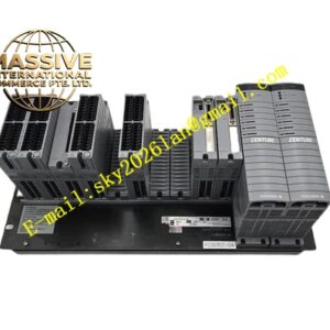
Structural Characteristics Vertical rack plug-in form factor compatible with Yokogawa ANB10 and ANB11 base racks. Front panel integrates power, communication and channel fault LED indicators. Rear gold finger connector mates with rack backplane for power supply and bus communication. External field wiring connects through dedicated MIL connector cables defined by the P60 option code. Side mechanical latch locks the module securely in the rack slot.
Working Principle Digital control setpoints sent by the DCS controller reach the module through the backplane bus. The onboard microcontroller sends digital values to high-resolution digital-to-analog converters. The converter circuits generate conditioned 4-20mA current signals for each output channel. HART modulation circuits overlay digital diagnostic and configuration data onto the analog current loop. The fault monitoring circuit continuously detects loop current and identifies open-circuit wiring faults.
Installation Requirements Cut off rack power before inserting or removing the module. Align the module with rack guide rails and push fully until the latch locks. Use matched MIL connector cables and shielded twisted-pair instrument cables for field actuator wiring. Configure output range and fail-safe mode in Yokogawa engineering software. Perform loop calibration and signal verification before process commissioning.
Precautions for Use Do not connect output channels to loads exceeding the maximum 750Ω resistance rating. Separate analog output cables from high-power inverter cables. Confirm HART device compatibility when connecting smart positioners. Implement anti-static protection during module handling outside the rack.