Description
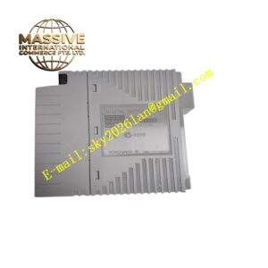
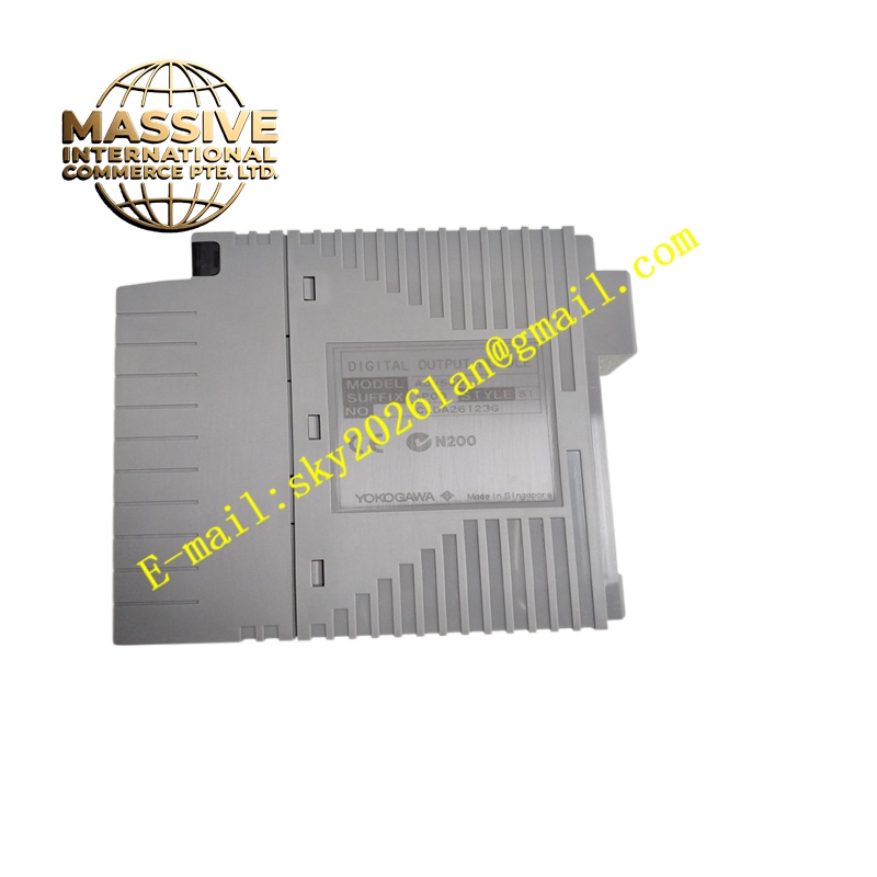
Yokogawa ADV569-P00
Technical Specifications 8 galvanically isolated analog output channels; 4 to 20mA output signal range; 16-bit digital-to-analog conversion resolution; basic accuracy ±0.1% full scale; maximum allowable load resistance 750Ω; isolation test voltage 1500V AC between field and system side; HART protocol support; operating temperature range -20°C to +70°C; IP20 protection rating.
Functional Features Converts digital control setpoints from the DCS controller into analog 4-20mA current signals to regulate field actuators. Supports HART communication to access valve positioner diagnostic data and remote parameter modification. Detects open-circuit faults on each output loop and sends fault alarms to the DCS system. Allows configuration of fail-safe output status when communication between the module and controller is interrupted. Transmits channel status and diagnostic logs to the controller through the rack backplane bus.
Application Scenarios Chemical batch reaction control, water treatment plant chemical dosing control, oil depot tank farm valve regulation, food and beverage production process control, pharmaceutical manufacturing automation.
Performance Parameters Minimal output drift over long continuous operation; high signal linearity across the entire output span; strong common-mode noise suppression for industrial cabinet environments; fast update speed for closed-loop regulatory control.
Material Composition Circuit board substrate uses FR-4 flame-retardant multilayer PCB; DAC chips and signal conditioning semiconductors are industrial wide-temperature components; isolation devices are high-reliability optocoupler amplifiers; backplane gold fingers use gold-plated copper contacts; outer casing is flame-retardant engineering plastic; terminal screws and contact springs are nickel-plated copper alloy.
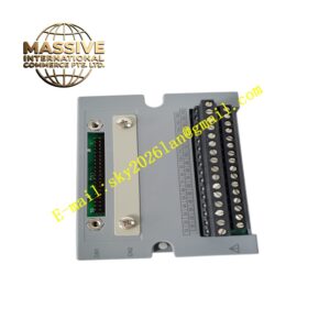
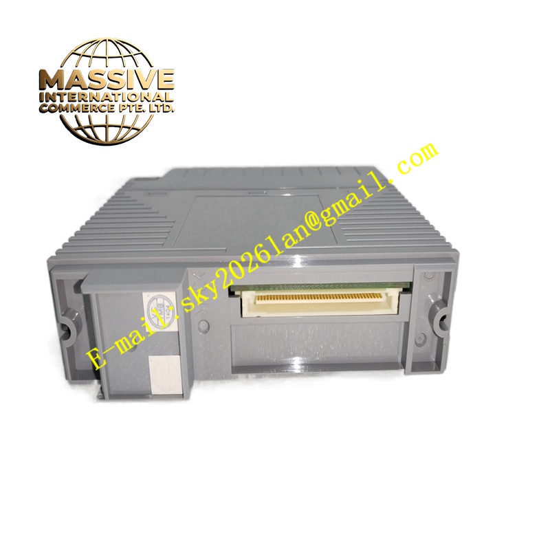
Structural Characteristics Compact vertical plug-in module compatible with Yokogawa CENTUM VP base racks. Front panel includes power LED, bus communication LED and channel fault indicators. Rear gold finger connector supplies module power and backplane bus data connection. Front terminal block accepts field wiring for actuators. Mechanical locking clip prevents loosening caused by cabinet vibration.
Working Principle Digital control values are transmitted from the CENTUM VP controller to the module over the backplane bus. The onboard processor passes the digital values to digital-to-analog converters. The converters generate analog current signals which go through filtering and isolation circuits to the field terminals. HART modulation circuits embed digital information on the analog loop. The monitoring circuit checks loop current continuously and triggers fault signals for open circuits.
Installation Requirements Power off the control rack before installing or replacing the module. Insert the module into the target slot and lock the retaining clip. Wire valve positioners and actuators to the terminal block with shielded twisted-pair cables. Set signal range and fail-safe state in Yokogawa engineering tool. Complete output signal calibration and loop test after power-on.
Precautions for Use Do not exceed the maximum load resistance for each output channel. Keep ventilation gaps of the module free of dust and conductive debris. Avoid routing analog signal cables alongside high-voltage power cables. Back up DCS configuration before module replacement.