Description
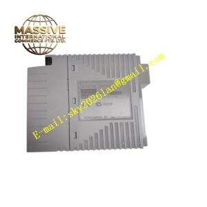
Yokogawa AVR10D-Q22020
Technical Specifications AC voltage input monitoring channel; supports specified AC voltage range; built-in voltage sampling and isolation circuit; digital communication interface for DCS backplane; 24V DC module auxiliary power supply; operating temperature -20°C to +70°C; IP20 protection rating; overvoltage and undervoltage threshold configurable.
Functional Features Sample AC voltage signals from monitored power circuits continuously. Convert sampled voltage signals into digital measurement data and calculate voltage RMS value. Judge whether voltage exceeds preset overvoltage or undervoltage threshold and generate alarm events. Transmit real-time voltage data and alarm status to the DCS controller through backplane bus. Record abnormal voltage event time and value into internal non-volatile memory. Conduct self-diagnosis of internal sampling circuit and power supply.
Application Scenarios Power plant auxiliary power monitoring, substation low-voltage circuit monitoring, chemical plant critical equipment power quality supervision, DCS cabinet power supply state monitoring, industrial key load power abnormality alarm.
Performance Parameters High RMS voltage measurement accuracy; fast abnormal voltage detection speed; stable sampling under power harmonic interference; complete event record retention after power loss.
Material Composition Main PCB uses FR-4 flame-retardant multilayer printed circuit board; voltage sampling and processing chips are industrial semiconductors; isolation transformers provide electrical isolation between monitored AC circuit and DCS internal circuit; backplane gold finger contacts use gold-plated copper alloy; module housing is flame-retardant thermoplastic resin; terminal contact springs use nickel-plated copper alloy.
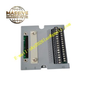
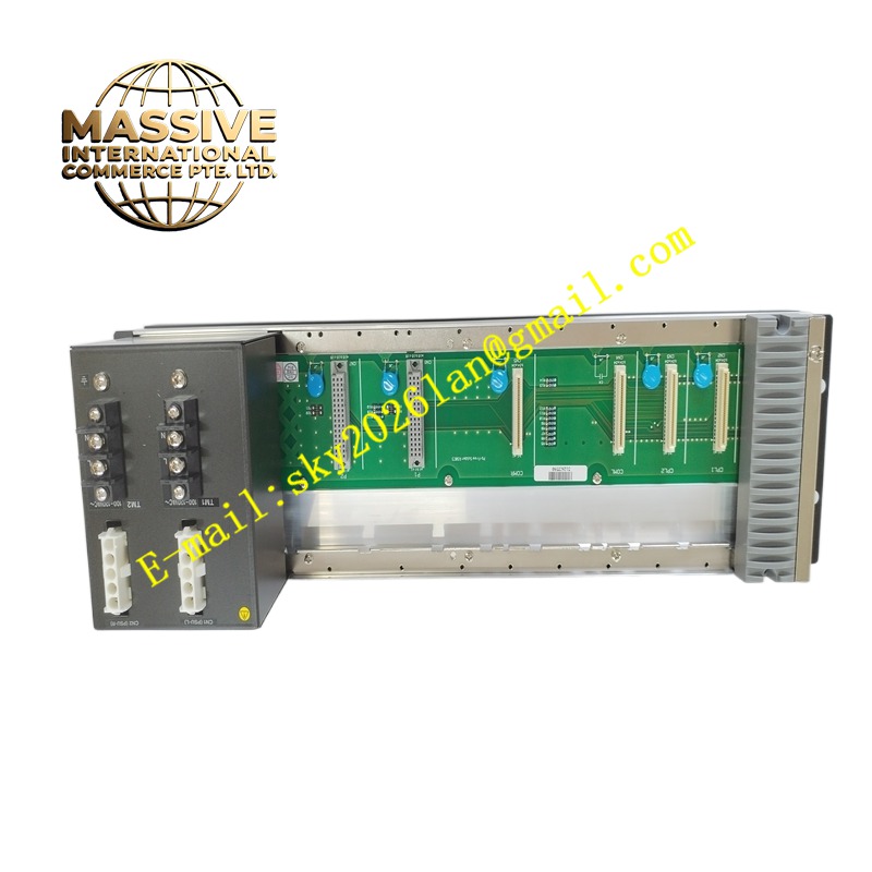
Structural Characteristics Vertical plug-in rack module compatible with Yokogawa DCS standard racks. Front panel has LED indicators for power, communication and voltage alarm status. Rear gold finger connector connects to rack backplane for bus communication and module auxiliary power supply. Front screw terminal blocks are used for monitored AC voltage wiring. Side mechanical latch locks the module in rack slots.
Working Principle Monitored AC voltage enters the sampling isolation circuit to separate high-voltage power circuit from low-voltage DCS control circuit. The onboard circuit calculates RMS voltage value and compares the value with user-configured threshold parameters. When voltage exceeds threshold range, the module generates alarm signals and uploads measurement data and alarm events to the DCS controller through the backplane bus.
Installation Requirements Cut off DCS rack power and monitored AC circuit power before module installation. Insert the module into the designated rack slot and lock the side latch. Wire monitored AC voltage signal to module input terminals following wiring specifications. Configure overvoltage and undervoltage alarm thresholds in Yokogawa engineering software. Test voltage measurement and alarm function after power restoration.
Precautions for Use Strictly match the input voltage range with monitored circuit voltage level. Isolate high-voltage monitored wiring from low-voltage DCS signal wiring. Perform regular calibration of voltage sampling channels. Take anti-static protection when handling the module.