Description
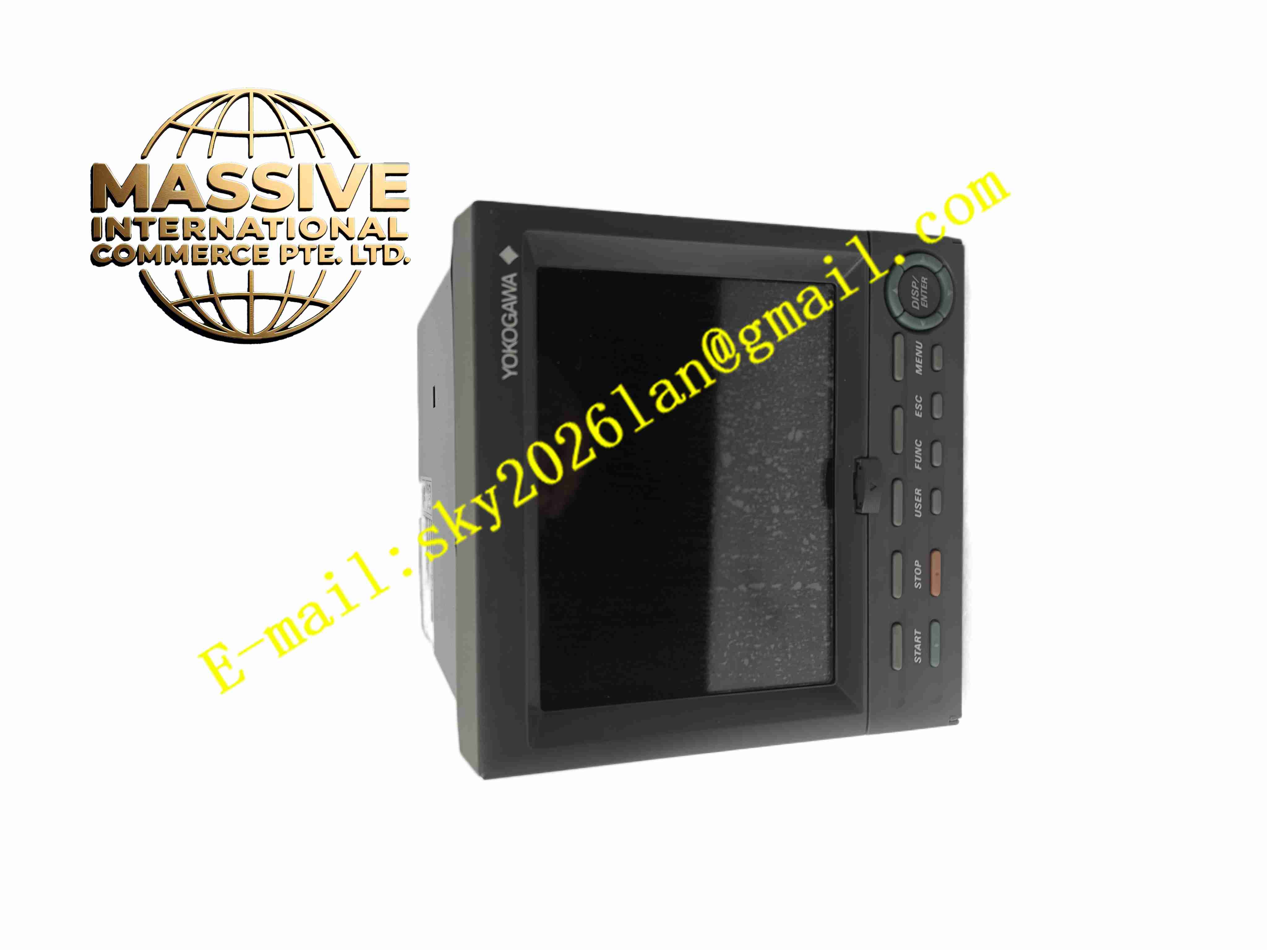
YOKOGAWA FX112 4-2
Technical Specifications:
- Number of Input Channels: 12 universal input channels
- Input Signal Types: Thermocouple, RTD, mV, 4–20 mA, 0–10 V DC
- Scan Interval: 1 second or 2 seconds selectable
- Display: Color LCD display
- Internal Memory: Large capacity flash memory for trend and event storage
- External Storage: SD card slot for data backup and export
- Communication Interfaces: RS232C, USB, optional RS422/485 Modbus
- Power Supply: AC 100 V to 240 V, 50/60 Hz
- Operating Temperature: -10 °C to +55 °C
- Storage Temperature: -20 °C to +70 °C
- Relative Humidity: 20% to 80%, non-condensing
- Mounting: Panel mount for control cabinet cutout installation
Function Features:
- 12-channel universal analog input for multiple process variables recording
- Real-time trend display, digital value display and bar graph display modes
- High-speed data sampling and long-term historical trend storage
- Event logging for alarm status, power on/off and operation events
- User configurable high/low alarm threshold for each channel
- Moving average digital filter to suppress high frequency signal noise
- SD card export for recorded data in standard file format
- Modbus communication option for data upload to DCS or SCADA
- Password protection for configuration and calibration parameters
Application Scenarios:
- Chemical reactor temperature and pressure trend recording
- Power plant boiler auxiliary process monitoring and recording
- Pharmaceutical batch manufacturing process data logging
- Water treatment plant continuous parameter recording
- Refinery auxiliary process condition monitoring
Material Composition:
- Front Panel: Flame retardant plastic with LCD protective window
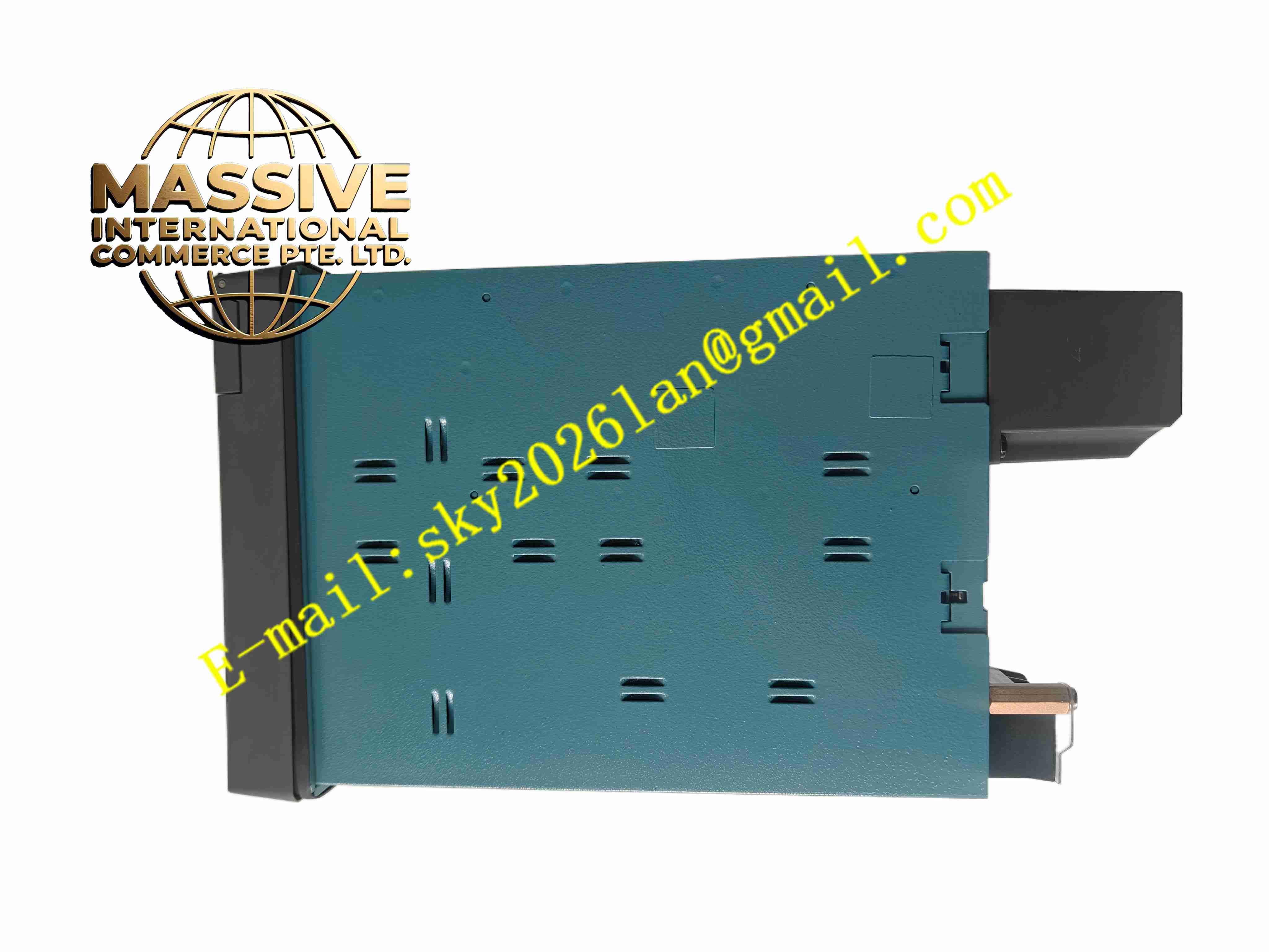
- Main Enclosure: Reinforced plastic rear housing
- Main PCB: Multilayer FR4 fiberglass printed circuit board
- Core Components: High precision analog front-end, microcontroller, flash memory
- Terminals: Screw copper terminal blocks for field sensor wiring
- Display Module: Color LCD panel with backlight
- Passive Components: Precision resistors, capacitors and surge protection devices
Structural Features:
- Panel mount design for cabinet cutout installation
- Front panel with LCD screen, operation pushbuttons and SD card slot
- Rear terminal block compartment for field sensor wiring
- Separate circuit zones for analog input, power and communication
- Plastic gasket on front panel for dust and splash resistance
- Quick release rear housing for easy wiring access
Working Principle: Field sensor signals including thermocouple, RTD and 4–20 mA enter the universal input terminals. The analog front-end circuit performs signal conditioning and isolation. The microcontroller samples each channel at selected scan interval, converts analog signals into engineering values and stores data into internal flash memory. Real-time trends and numerical values render on LCD screen. When process value exceeds preset threshold, alarm events record into event log. Stored data can be exported via SD card or uploaded via serial communication to upper systems.
Installation Requirements:
- Cut cabinet panel to match FX112 mounting dimension
- Insert recorder from front and fasten mounting clips
- Use shielded twisted pair cables for field sensor wiring
- Separate low-level sensor cables from high voltage power cables
- Connect AC power supply and protective earth
- Keep ambient temperature between -10 °C and +55 °C
- Avoid installation location with direct sunlight and heavy vibration
Usage Notes:
- Select correct input sensor type and engineering unit for each channel before commissioning
- Perform channel calibration periodically to maintain measurement accuracy
- Backup recorded data to SD card regularly
- Use password to restrict unauthorized modification of configuration
- Disconnect AC power before opening rear terminal cover
- Check sensor wiring polarity to avoid reversed signal reading