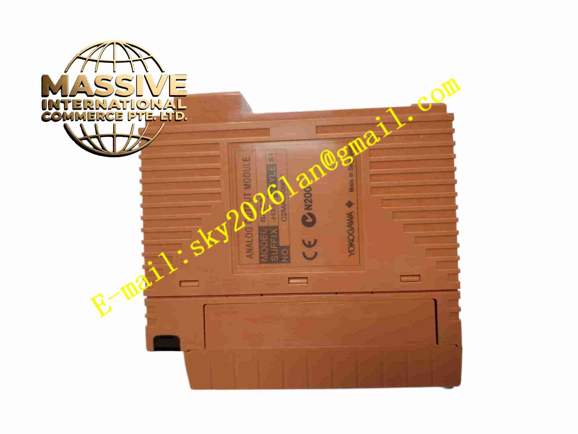
Description
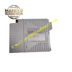
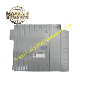
YOKOGAWA SAI533-H33
Technical Specifications
- Brand: Yokogawa
- Model: SAI533-H33
- Product type: Analog output module
- Output signal: 4 to 20 mA DC
- Number of channels: 8 channels
- Isolation: Module isolation
- Communication: HART communication supported
- Temperature rating: -20 °C to +70 °C with ISA Standard G3 option
- Connection style: Signal cable interface adapter configuration
- System compatibility: Yokogawa ProSafe-RS and related Yokogawa I/O systems
- Mounting: Installed in a Yokogawa I/O node or rack
- Status indication: Module and channel LEDs for power, output and fault status
Functional Features
- Provides 8 isolated analog output channels.
- Converts controller output values into precise 4 to 20 mA signals.
- Supports HART communication for compatible field devices.
- Offers module-level isolation for improved signal integrity.
- Integrates with Yokogawa safety and process control architectures.
- Supports diagnostic monitoring and module status indication.
- Suitable for control valve positioning and analog actuator control.
- Designed for long-term operation in harsh industrial environments.
Application Scenarios
- Control valve output in process plants.
- Analog actuator and damper control.
- Safety system final element control.
- Petrochemical and chemical process control.
- Power plant control and protection systems.
- Oil and gas facility automation.
- Pharmaceutical and food process systems.
- Industrial plants requiring reliable analog output signals.
Performance Parameters
- 8-channel 4 to 20 mA analog output.
- Module isolation between field and system circuits.
- HART communication capability for compatible devices.
- Operating temperature range -20 °C to +70 °C with the -33 environmental option.
- Signal cable interface adapter connection for the -H33 configuration.
- Typical accuracy around ±16 µA and allowable load resistance up to about 750 Ω in common SAI533 configurations, but exact values must be confirmed from the Yokogawa manual and nameplate.
- Exact output accuracy, update rate, load drive capability, fault response behavior, HART channel details and certification data should be verified in official Yokogawa documentation.
Material Composition
- Industrial-grade printed circuit board.
- Digital-to-analog conversion circuits.
- Current output driver circuits.
- HART communication interface.
- Isolation components.
- Backplane connector for rack mounting.
- Signal cable interface adapter terminals.
- Status LEDs, module label and protective housing.
Structural Features
- Modular I/O card structure.
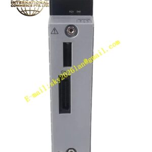
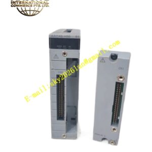
- Connection through a signal cable interface adapter.
- LED indicators for module power, channel output and fault conditions.
- Clear model, channel and revision markings.
- Designed for Yokogawa I/O rack installation.
- Compatible with KS-type or Yokogawa-standard cabling.
- Compact front profile suitable for dense control cabinet layouts.
Working Principle
The SAI533-H33 receives digital output values from the Yokogawa controller and converts them into proportional 4 to 20 mA current signals. Each channel drives the connected field device according to the controller output. Module isolation helps prevent ground interference between the control system and field wiring. When HART communication is used, the module can support bidirectional communication with HART-enabled devices for diagnostics, configuration or status verification. The module continuously monitors output status and reports faults to the host system.
Installation Requirements
- Install in a compatible Yokogawa I/O rack or node.
- Remove power before inserting or removing the module.
- Use the correct signal cable interface adapter for the -H33 configuration.
- Verify loop power and load resistance before commissioning.
- Keep analog output wiring separate from power cables.
- Follow Yokogawa grounding, shielding and cable routing rules.
- Confirm HART configuration only when the field loop supports HART.
- Check module LEDs after system startup.
Precautions for Use
- Do not short-circuit or open-circuit output channels during operation without reviewing system requirements.
- Do not exceed the specified load resistance.
- Replace only with the correct Yokogawa model and revision.
- Investigate output faults before forcing valve positions.
- Keep connectors clean and properly seated.
- Maintain accurate records of HART device addresses and loop configurations.
- Follow safety system maintenance procedures when used in ProSafe-RS applications.
- Refer to the official Yokogawa SAI533 and ProSafe-RS manuals for detailed wiring and diagnostics.