Description
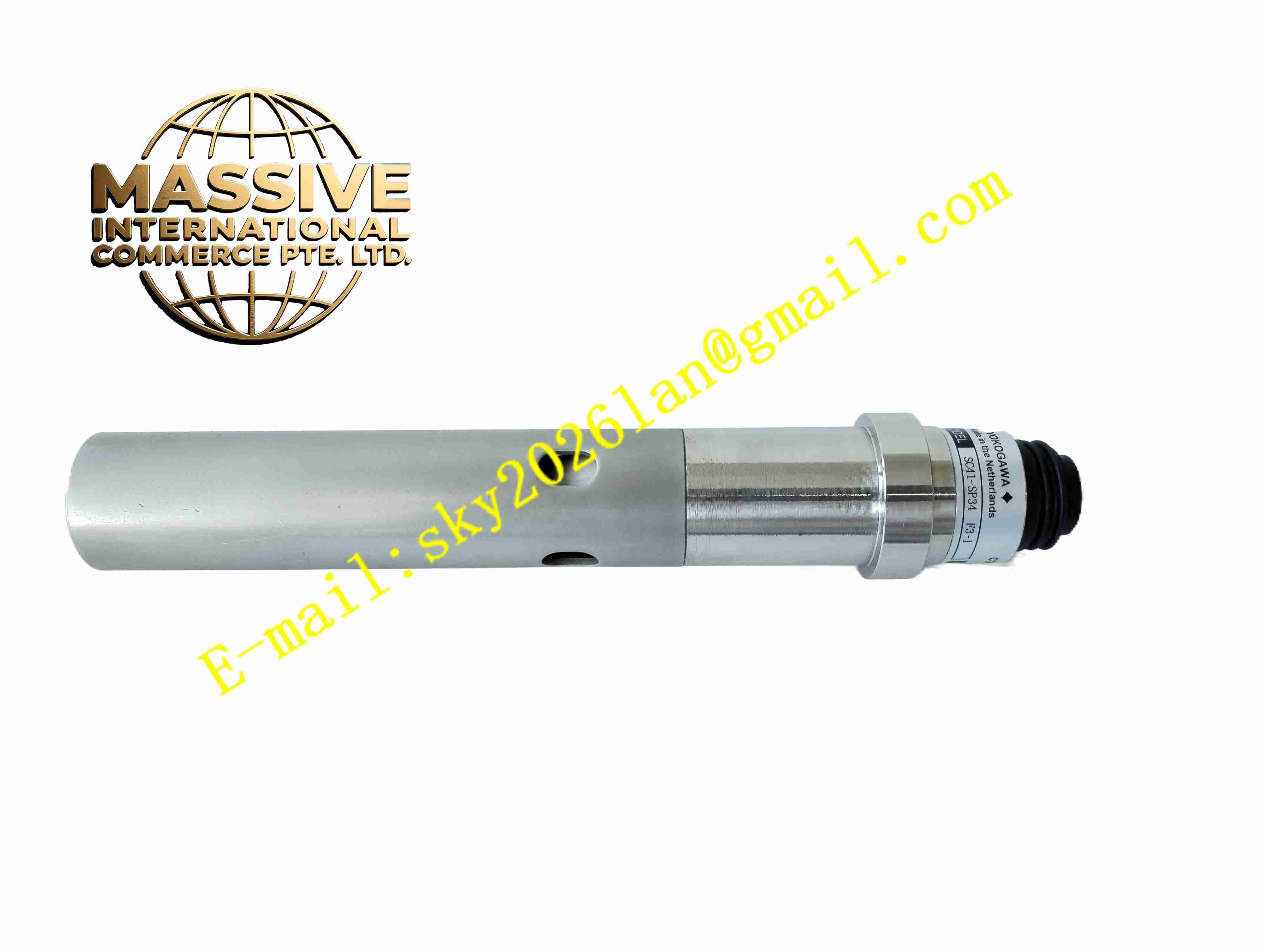
Yokogawa SC41-SP34
Technical Specifications: CPU architecture: 32-bit industrial RISC processor Memory: On-board flash program storage and SRAM data memory Control loop capacity: Up to 64 PID loops Digital I/O: On-board integrated discrete I/O channels Communication ports: Serial RS-232C and RS-485 Power supply: 24 VDC rated Operating temperature: -10 ℃ to 55 ℃ Storage temperature: -25 ℃ to 70 ℃ Relative humidity: 5% to 95% non-condensing Mounting: DIN rail or panel mount
Functional Features: Standalone PID and sequence control execution. Ladder logic and function block programming support. Built-in EEPROM retains user program and configuration parameters after power loss. Self-diagnostic routines detect CPU, memory and communication faults. Watchdog timer triggers safe output state upon program runaway. Front-panel LED indicators show power, run and alarm status. Modbus RTU protocol communication for upper-system integration. Hot-swappable I/O expansion capability.
Application Scenarios: Small-scale water treatment plant control unit, packaging machine sequence controller, building HVAC control cabinet, food and beverage process monitoring station, compact pump station control system.
Performance Parameters: Control scan cycle: configurable from 100 ms to 2 s Backplane communication rate: 115.2 kbps maximum Power consumption: 5 W typical Vibration resistance: 10 Hz to 150 Hz, 0.25 g Shock resistance: 10 g peak acceleration
Material Composition: Module housing: UL94-V0 flame-retardant engineering plastic. PCB substrate: FR-4 glass fiber epoxy board. Terminal blocks: nickel-plated brass. Mounting clip: stainless steel.
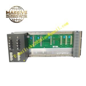
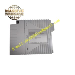
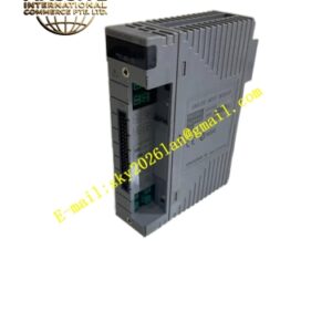
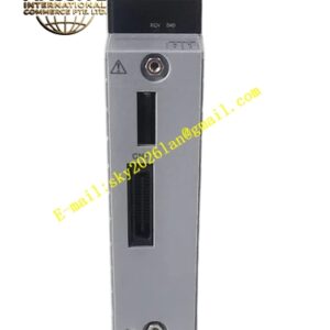
Structural Features: Compact DIN-rail mount housing. Front panel with LED status indicators and configuration port. Removable screw-type terminal blocks. Internal PCB partitions separate CPU logic area and power supply filtering area.
Working Principle: The CPU executes user-downloaded control program cyclically. Input channels read field device states, logic operations evaluate conditions, output channels drive field actuators. Communication interface exchanges data with upper monitoring host. Self-diagnostic circuit monitors internal operation continuously.
Installation Requirements: Mount on standard 35 mm DIN rail inside control cabinet. Route communication cables separately from power cables. Ensure cabinet protective grounding is complete. Reserve wiring space around terminal blocks.
Precautions for Use: Do not apply voltage exceeding rated input. Wear anti-static wristband during configuration. Keep module away from high-vibration equipment. Back up user program before firmware update. Do not install in corrosive gas environment.