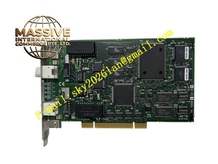
Description
YOKOGAWA VF701
Technical Specifications: Model: VF701 Input signal type: Pulse signal, frequency signal, tachometer signal Input channel quantity: Multiple isolated pulse input channels Power supply: 24VDC from DCS backplane Frequency measurement range: 0Hz to 100kHz Isolation: Galvanic isolation between field side and DCS internal circuit Operating temperature: 0℃ to +60℃ Storage temperature: -20℃ to +70℃ Relative humidity: 5% to 95%, non-condensing Mounting: DCS rack plug-in module
Functional Features: Field pulse and frequency signal acquisition from tachometer and pulse output flow meters. High resolution frequency calculation and pulse totalization function. Galvanic isolation between field wiring and DCS internal circuit. Overvoltage and surge protection for field input channels. Signal quality diagnosis for open circuit and abnormal pulse signal. Transmit frequency value and accumulated pulse count to DCS controller. Support configurable pulse scaling for engineering unit conversion.
Application Scenarios: Power plant turbine shaft speed measurement, flow totalization for oil and gas pipeline, water treatment flow meter pulse acquisition, rotating machinery tachometer signal collection, chemical plant batch flow counting, pulp and paper machine speed monitoring.
Performance Parameters: High frequency measurement accuracy across full frequency range. High speed pulse counting without pulse loss. Galvanic isolation blocks ground loop interference. Continuous stable counting during long term plant operation.
Material Composition: FR4 industrial printed circuit board. Pulse signal shaping and isolation components. High speed counter chips. Surge protection circuit elements. Flame retardant plastic front panel with LED indicators. Gold plated backplane connector.
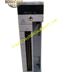
Structural Features: Standard plug-in module for Yokogawa DCS rack. Front panel LED indicators for channel status and fault. Front screw terminal blocks for field pulse sensor wiring. Internal galvanic isolation barrier separates field circuit and DCS side circuit. Compact module design for DCS cabinet rack installation.
Working Principle: Field pulse signal from tachometer or flow meter enters VF701 module through screw terminals. Signal conditioning circuit shapes pulse waveform and provides galvanic isolation. High speed counter chip counts pulse number and calculates input frequency. The module converts frequency value to engineering value according to scaling parameter. Digital data transfers to DCS controller via rack backplane bus. Built-in diagnostic circuit monitors pulse signal status and reports channel fault to DCS system.
Installation Requirements: Insert VF701 module into designated slot of Yokogawa DCS rack. Use shielded twisted pair cable for pulse sensor wiring. Separate pulse signal cables and high power cables. Tighten terminal screws to specified torque. Install DCS rack in IP20 air conditioned control cabinet. Complete protective earth bonding for rack chassis.
Usage Notes: Set pulse scaling and filter parameters during DCS configuration. Verify pulse amplitude matches module input requirement. Power off rack before removing module. Check terminal connection tightness periodically. Test pulse counting function after wiring modification.