Description
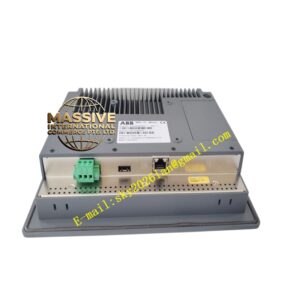
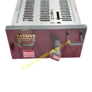
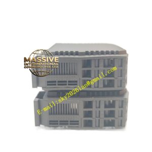
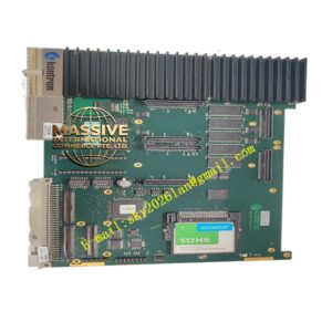
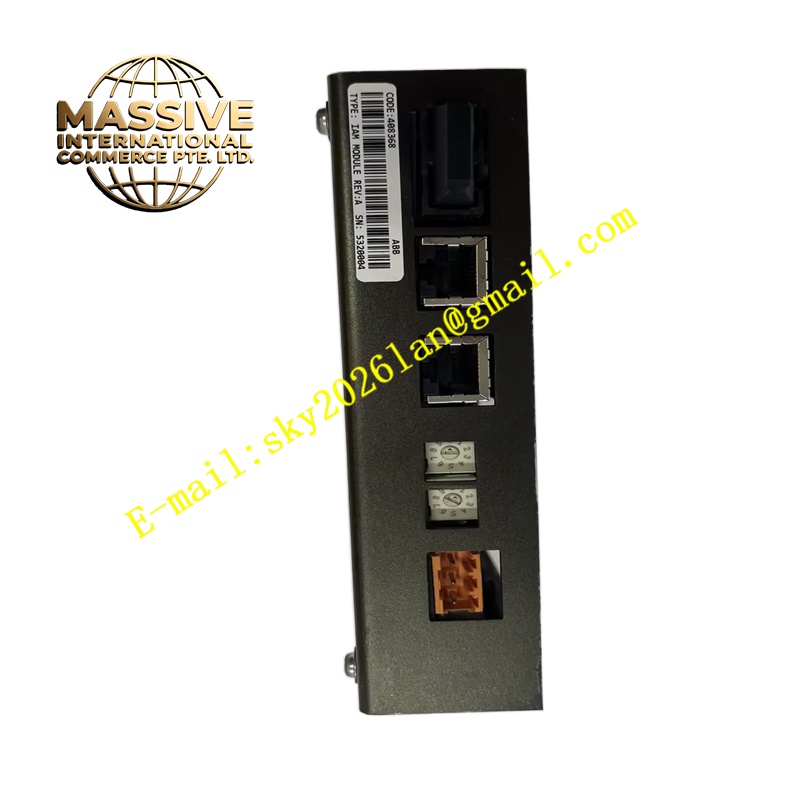
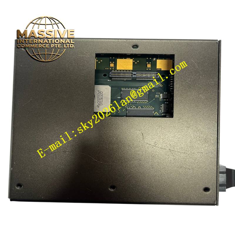
ABB 408368 IAM MODULE
Technical Specifications Multi-channel signal input design; built-in signal isolation circuit; support for standard analog and digital field signals; powered by system backplane bus; equipped with status LED indicators; DIN rack installation structure.
Functional Features Conditions raw signals transmitted from field sensors and transmitters. Isolates field side and control side circuits to suppress ground loop interference. Filters high-frequency noise mixed in field wiring. Uploads channel diagnostic information including open circuit and short circuit faults to the host controller. Transmits standardized signals to the main control board through the backplane bus.
Application Scenarios Power plant auxiliary control systems, chemical process control systems, water treatment automation systems and ABB distributed control system racks.
Performance Parameters High signal conversion accuracy; low signal attenuation; stable isolation performance; fast fault diagnosis response speed.
Material Composition Circuit substrate is FR-4 flame-retardant multilayer printed circuit board; isolation components adopt industrial optocoupler chips; backplane connector contacts are gold-plated; module housing is flame-retardant thermoplastic.
Structural Characteristics Rectangular plug-in card structure matching ABB standard control rack; front panel with channel status LED lights; rear gold finger connector connecting with rack backplane; fixed by locking screws on the front panel.
Working Principle Field signals enter the module through terminal wiring. Signals pass through filtering and isolation circuits to eliminate interference. The signal conditioning circuit converts raw signals into digital data recognizable by the main controller. The module communicates fault and status information to the host controller via the backplane bus.
Installation Requirements Cut off the power supply of the control rack before installation. Insert the module into the designated slot of the ABB rack and tighten the front locking screws. Complete field signal wiring according to the terminal definition. Conduct channel function verification after power restoration.
Precautions for Use Follow anti-static operating procedures during disassembly and installation. Hot plugging of the module is forbidden. Signal cables must be laid separately from high-voltage power cables. Replace the module immediately when persistent hardware faults occur.