Description
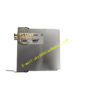
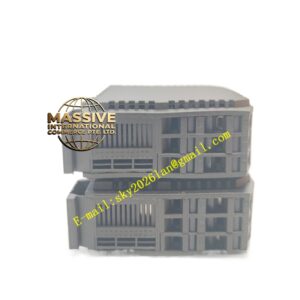
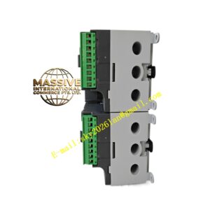
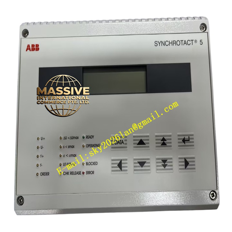
ABB TB521-ETH
- Technical Specifications:
- Compatible I/O Modules: All S800 I/O (DI8xx, DO8xx, AI8xx, AO8xx, DP8xx, TP8xx…) — max 12 modules per TB521 (some high-density or special modules may limit to fewer — check total 5 V current budget)
- ModuleBus: Connects to AC 800M CPU baseplate (BC810/BC820) via flat ribbon cable (TK801V006etc.) for local I/O; OR connects to CI840A (mounted on TB521) for remote I/O (HN800 bus)
- Power Connections: Accepts 24 V DC from plant PSU → PPD113A01 (mounts on left of TB521) → distributes 5 V logic & UP to modules
- DIN Rail: 35 mm (EN 60715) — top & bottom DIN clips on TB521
- Dimensions (TB521 alone): ≈45 mm (W, per module slot) × 119 mm (H) × 102 mm (D) — actual width = 45 mm × (1 + #modules) when populated
- Material: Glass-fiber reinforced polyamide (PA66), UL 94 V-0; nickel-plated brass PE bar
- Operating Temp.: –20 °C to +55 °C (same as S800 modules)
- Certifications: CE, UL, cUL, ATEX Zone 2 (with system cert), marine (DNV/ABS/LR)
- Max 5 V Logic Current (total rack): Typically ≤3 A (depends on PPD113 version — PPD113A01 provides up to 3 A 5 V)
- Functional Features:
- Hot-swappable I/O modules (with controller scan support)
- Keyed end-plate prevents mismating of different S800 generations (S800 vs S900 — different key)
- Integrated strain relief for bus cable & power cables
- Grounding bar ensures star-point earthing of all modules’ PE connections
- Application Scenarios:
- Forms the base of every S800 I/O rack — local (direct ModuleBus to AC 800M) or remote (CI840A + HN800)
- Used in System 800xA, Freelance (with AC 800M PM9xxF + CI840A), and Advant OCS migration (CI520A + S100→S800 retrofit)
- -ETH preferred in Ethernet-rich panels for better cable management of RJ45 from CI840A
- Material & Structure:
- Molded glass-filled nylon base with integral aluminum or brass PE busbar
- Spring-steel DIN clips (top & bottom)
- Printed circuit bus bars (5 V, 24 V UP, AGND) embedded in molding — gold-plated contacts mate with module edge-fingers
- End plates (left & right) — one for PPD113 side, one for last I/O module — keyed
- Working Principle:
When an module is snapped into , its gold-edge connector mates with the embedded bus bars → 5 V logic, 24 V process (UP), and PE are immediately available. The CI840A(if present) communicates with modules via the ModuleBus lines on the backplane. For local I/O, a TK801V006 flat cable links the ModuleBus header to the AC 800M CPU baseplate’s ModuleBus header — the CPU directly scans I/O images each cycle.
- Installation Requirements:
- Mount -ETH on 35 mm DIN rail — ensure DIN clips engage; leave ≥50 mm top/bottom for ventilation & cable bending
- Snap in PPD113A01 power module (leftmost position) → connect 24 V DC incoming power (A/B redundant if used) to PPD terminals → verify 5 V OK LED on PPD
- Snap in I/O modules (DI830, DO820, AI835…) into subsequent slots — they self-seat on bus bars
- Install CI840A(if remote I/O) onto its DIN clip / header on or into CEX slot on AC 800M baseplate (for local I/O no needed — just ModuleBus cable)
- For local I/O: connect TK801V006 ModuleBus cable between ModuleBus header & AC 800M CPU baseplate ModuleBus header
- For remote I/O: connect HN800 fiber/copper from to upstream switch / controller
- Wire field signals to I/O module terminals per channel assignment
- In Control Builder M / Freelance: define I/O station → assign module types → download → verify Com LED on (remote) or Run LED on CPU (local)
- Terminate HN800 bus with 120 Ω resistor (built-in jumper on CI840Aor external) at both ends
- Precautions:
- ESD: Although modules are hot-swappable, handle by edges; touch DIN rail / cabinet earth before touching module edge-connector
- Ensure 24 V DC supply polarity correct & fused (typical 2–5 A slow-blow per PSU)
- Do NOT exceed total 5 V current draw of rack — sum module logic currents (typ. 80–150 mA/module) ≤ PPD113 5 V rating (3 A typical) — if close to limit consider splitting into two racks / using PPD115 (higher current)
- Verify module keying matches ( modules have key on bottom — has corresponding notch; S900 won’t fit)
- Always terminate HN800 / ModuleBus at both ends — missing termination = CRC errors / intermittent dropouts