Description
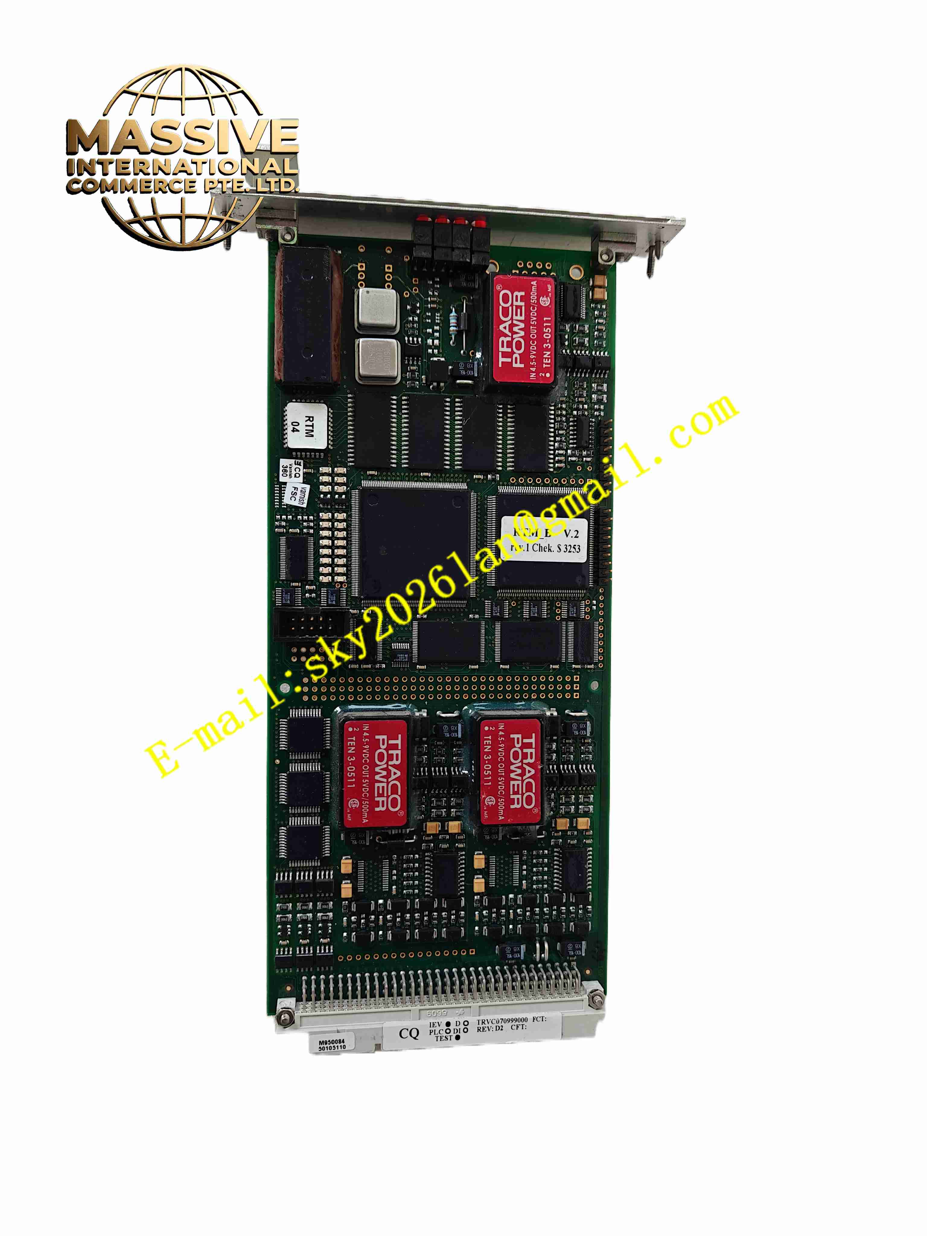
ALSTOM NRD108031 TRVC070999000 BOTTOM
Technical Specifications: Model identifier: NRD108031, TRVC070999000 Product type: Rack bottom base assembly Mounting method: Cabinet rack fixed installation Material mechanical rating: Industrial heavy vibration resistant grade Operating temperature range: -10℃ ~ +60℃ Storage temperature range: -40℃ ~ +85℃ Relative humidity: 5% to 95%, non-condensing Protection grade: IP20 when fully assembled in cabinet Compatibility: Matches Alstom TRVC series control rack
Functional Features: Provide mechanical base support for full height control rack and all plug-in modules. Fix and carry system backplane board at rack bottom position. Provide internal cable routing channel for signal and power wiring. Mechanical positioning guide for plug-in modules during insertion. Reinforced structure to absorb vibration and protect internal backplane and modules. Equipped with grounding bus bar for rack equipotential bonding. Reserve installation holes for terminal blocks and cable glands. Support cabinet cooling air flow distribution for rack internal ventilation.
Application Scenarios: Thermal power plant turbine control cabinet, hydroelectric power plant automation rack, railway signal control cabinet, legacy Alstom power generation control system renovation, substation auxiliary control cabinet, heavy industry process control rack upgrade project.
Performance Parameters: High mechanical rigidity to maintain rack geometry under continuous vibration. Long service life for 24 hours continuous operation inside industrial control cabinet. Stable equipotential grounding performance for entire control rack. Mechanical strength meets power plant and railway vibration test standard.
Material Composition: Main structural frame: Cold rolled steel plate with anti-corrosion powder coating. Backplane mounting bracket: Galvanized steel sheet. Grounding bus bar: Tinned copper bus bar. Fasteners: Zinc plated carbon steel screws and locking washers. Insulation components: FR4 insulation sheet and PA66 flame retardant plastic spacers.
Structural Features: Welded and bolt assembled rectangular bottom frame structure. Precision positioning guide rails for vertical insertion of plug-in modules. Backplane mounting support brackets fixed on rear side of base frame. Integrated copper grounding bar along base edge for rack grounding connection. Cable routing trough inside base for orderly wiring arrangement. Multiple mounting holes for fixing base onto cabinet floor. Mechanical stop limit structure to prevent module over insertion.
Working Principle: This product is passive mechanical assembly without electronic circuit. It forms the bottom foundation of Alstom TRVC series control rack. The base frame bears total weight of backplane and all plug-in modules. Guide rails align each module during insertion, and backplane fixed on rear bracket provides electrical bus connection between modules. Copper grounding bar connects rack, backplane and module shielding together to build equipotential grounding network. Internal cable trough organizes all incoming and outgoing wires to reduce cable stress and electromagnetic crosstalk. The rigid steel structure absorbs external vibration from site environment to protect delicate electronic modules installed above.
Installation Requirements: Install base assembly onto cabinet floor using specified fixing bolts and locking washers. Level the base frame and adjust mounting position to align vertical guide rails. Mount backplane board onto rear brackets of bottom base and fasten all fixing screws. Connect copper grounding bar to cabinet protective earth ground with short thick grounding cable. Arrange power and signal cables inside internal cable routing trough. Check guide rail vertical alignment before installing electronic modules. Ensure no mechanical deformation on frame after tightening all fasteners.
Usage Notes: Inspect frame deformation and coating damage before installation. Do not overload rack beyond total rated weight capacity. Regularly check fastener tightness under continuous vibration environment. Maintain grounding bus bar surface free from corrosion and oxidation. Prevent metal debris and conductive dust accumulation inside base cable trough. Do not modify welded frame structure by cutting or drilling extra holes. Keep ventilation path inside base free from blockage to maintain rack cooling airflow.