Description
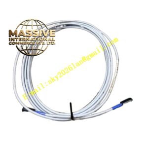
Bently 330103-00-06-10-02-0
Technical Specifications
- Product Series: 3300 XL 8mm Eddy Current Sensor System
- Probe Diameter: 8 mm (0.315 inches)
- Sensitivity: 200 mV/mil (7.87 V/mm)
- Thread Specification: M10 x 1 Metric Thread
- System Length: 3.0 meters (10 feet) total system length
Functional Features
- Extended Reach: Designed for applications requiring longer system lengths without signal degradation.
- Non-Contacting Measurement: Eliminates mechanical wear on the sensor, providing the most direct and reliable shaft motion information.
- API 670 Compliant: Meets stringent industry standards for mechanical vibration monitoring and protection.
Application Scenarios
Ideal for large-scale rotating equipment such as pumps, fans, and gearboxes in oil refineries and power plants where the monitoring cabinet is situated at a moderate distance from the machinery bearings.
Performance Parameters
- Linear Measurement Range: 80 mils (2.0 mm)
- Frequency Response: 0 to 10 kHz (-3 dB)
- Operating Temperature Range: -52°C to +177°C (-62°F to +350°F)
- Supply Voltage: -24 VDC nominal
Material Composition
Manufactured with high-grade 316L stainless steel for the probe body and high-temperature FEP insulation for the internal cabling, ensuring longevity in aggressive industrial atmospheres.
Structural Characteristics
Incorporates ClickLoc gold-plated copper connectors that lock securely with a finger-tight plus 1/8 turn mechanism, preventing accidental loosening in high-vibration environments.
Working Principle
Utilizes high-frequency electromagnetic induction. The proximity of the conductive target alters the eddy current losses in the probe coil, which is translated into a linear voltage output representing the physical gap.
Installation Requirements
Ensure the mounting surface is clean and free of burrs. Use the specified torque values for the M10 thread to prevent mechanical distortion. Verify system continuity and insulation resistance prior to energizing.
Usage Precautions
Avoid routing the extension cable parallel to high-voltage power lines to prevent electromagnetic interference. Periodically calibrate the system using a TK-3E calibrator to verify linearity and sensitivity.