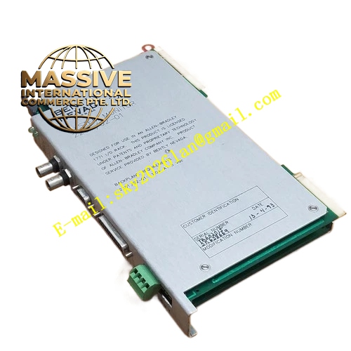
Description
Bently 330180-05-00
Technical Specifications
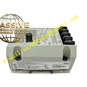
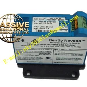
- Product Series: 3300 XL 8mm Proximitor Sensor
- Part Number: 330180-05-00
- System Length: 5.0 meters (16.4 feet)
- Mounting Style: Panel mount
- Agency Approval: Not required (standard version)
- Power Supply: -17.5 to -26 Vdc (without safety barrier); -23 to -26 Vdc (with safety barrier)
- Maximum Current: 12 mA
- Output: Voltage or current signal with output short-circuit protection
- Output Impedance: 50Ω
Functional Features
- Signal Conditioning: Receives the high-frequency signal from the 3300 XL 8mm proximity probe and extension cable, demodulates the impedance change, and converts it into a linear DC voltage output proportional to the gap distance.
- Dual Measurement Capability: The output voltage contains both a DC component (for static displacement/position measurement) and an AC component (for dynamic vibration measurement), enabling simultaneous monitoring of shaft position and vibration.
- Strong Anti-Interference: Improved RFI/EMI immunity meets European CE electromagnetic compatibility standards, allowing installation in fiberglass enclosures without being affected by nearby radio frequency signals. No special shielded conduits or metal enclosures are required.
- Panel Mount Design: Traditional four-hole panel mounting configuration, compatible with existing 3300 series mounting hole patterns. The mounting base provides electrical insulation, eliminating the need for a separate isolation plate.
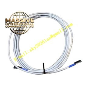
- Full Interchangeability: All 3300 XL 8mm Proximitor sensors, probes, and extension cables are fully interchangeable without the need for individual matching or bench calibration.
- Backward Compatibility: Compatible with other non-XL 3300 series 5mm and 8mm sensor system components.
Application Scenarios
Widely used in power generation, petrochemical, refining, steel, and chemical industries for vibration monitoring of large and medium-sized rotating machinery. Typical applications include steam turbines, gas turbines, centrifugal compressors, pumps, fans, motors, generators, gearboxes, and water turbines. The system measures shaft radial vibration, axial displacement, keyphasor, rotational speed, and differential expansion in oil-film bearing machines. The 5.0 meter system length is suitable for installations where the Proximitor is mounted at a moderate distance from the probe.
Performance Parameters
- Linear Range: 2 mm (80 mils), starting from approximately 0.25 mm (10 mils) from the probe face
- Sensitivity: 7.87 V/mm (200 mV/mil)
- Frequency Response: 0 to 10 kHz (typical +0 to -3 dB)
- Linear Deviation: Less than ±0.31 mm (±12 mils)
- Recommended Gap Setting: 1.27 mm
- Minimum Target Size: 15.2 mm diameter
- Minimum Shaft Diameter: 76.2 mm (3 inches)
- Proximitor Operating Temperature: -35°C to +85°C
- Proximitor Storage Temperature: -35°C to +100°C
Material Composition
Cast aluminum housing with hard anodized surface treatment, internal circuit board with conformal coating for moisture protection, and SpringLoc terminal block for field wiring connections.
Structural Characteristics
The Proximitor features a compact cast aluminum enclosure designed for panel mounting. The SpringLoc terminal block allows secure field wiring connections without the need for special installation tools. The screwless terminal design prevents loosening over time, ensuring reliable long-term connections. The mounting base provides built-in electrical insulation.
Working Principle
The Proximitor’s internal oscillator circuit generates a high-frequency current (typically 1-2 MHz) that flows through the extension cable to the probe coil. This current creates a high-frequency alternating magnetic field around the probe tip. When a conductive target surface enters this field, eddy currents are induced in the target, generating a magnetic field in the opposite direction to the probe coil’s field. This opposing field changes the effective impedance of the probe coil. The Proximitor’s detection circuit monitors this impedance change, demodulates and amplifies it, and converts it into a DC voltage output that is linearly proportional to the gap distance. The DC component of the output represents static displacement, while the AC component represents dynamic vibration.
Installation Requirements
Mount the Proximitor on a panel using the four-hole mounting pattern. Connect the extension cable from the proximity probe to the Proximitor input terminal. Connect the output signal cable to the monitoring system (such as Bently 3500 series modules). Verify the power supply voltage is within the specified range before energizing. Ensure the total system electrical length (probe cable plus extension cable) matches the 5.0 meter Proximitor rating. The mounting base provides electrical insulation, so no separate isolation plate is required.
Usage Notes
Verify the input voltage is correct before powering up to prevent equipment damage. Check all connector and terminal connections are secure. The Proximitor is calibrated for AISI 4140 steel target material; if a different target material is used, recalibration is required. Ensure the target surface is clean and free of debris. Route signal cables away from high-energy power cables with a minimum separation of 30 cm. Avoid exposing the Proximitor to temperatures exceeding the rated operating range.