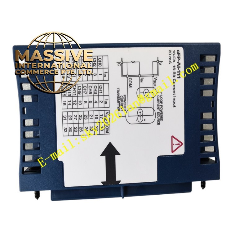
Description
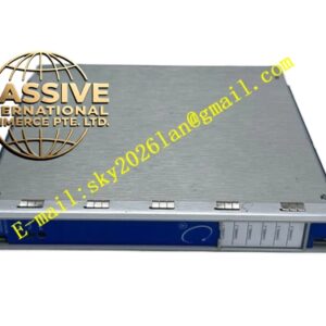
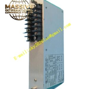
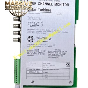
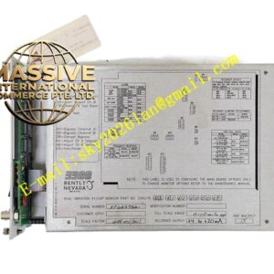
Bently 990‑04‑05‑02‑00
Technical Specifications:
- Compatible Sensor: 3300 NSv series proximity probe and extension cable, total electrical length 5 m
- Measured Parameter: Shaft radial peak‑to‑peak vibration
- Full‑Scale Measurement Range: 0‑1 mm peak‑to‑peak
- Power Supply Mode: Two‑wire loop power supply, +12 VDC ~ +35 VDC
- Output Signal: 4‑20 mADC two‑wire
- Loop Accuracy: ±1.5% full‑scale
- Frequency Response: 5 Hz ~ 6000 Hz (+0 /‑3 dB)
- Prox‑Out Diagnostic Terminal: Available for gap‑voltage measurement
- Maximum Loop Resistance: 1000 Ω @35 VDC
- Mounting Method: 35 mm DIN‑rail clip or panel screw mounting
- Operating Temperature: ‑40 °C ~ +85 °C
- Humidity: 0‑95% RH non‑condensing
- Startup Inhibition: Output holds below 3.6 mA within initial 2‑3 seconds after power‑on Functional Features:
- Fully integrated proximitor circuit. NSv probe connects directly to transmitter without external proximitor hardware.
- Two‑wire loop design, same pair of cables provide power supply and 4‑20 mA signal transmission, reduces field wiring workload.
- Zero and span potentiometers accessible on unit housing for on‑site loop calibration.
- Dedicated test‑input terminal allows loop function verification without real sensor connection.
- Built‑in sensor fault detection circuit. Upon probe open‑circuit or short‑circuit fault, output locks to defined NOT‑OK current level to avoid false alarm from control system.
- Prox‑Out diagnostic terminal provides raw gap‑voltage for field troubleshooting of probe and cable faults.
- Potted sealed construction, adapts to high‑humidity industrial cabinet environment. Application Scenarios: Radial shaft vibration monitoring for compressors, fans, pumps; machinery modification projects without TSI rack hardware; OEM equipment matching; hazardous‑area field vibration signal conversion feeding DCS/PLC system. Performance Parameters: Linear error ≤ ±1.5% FS; fault response time <200 ms; strong immunity to industrial electromagnetic interference; low temperature drift within operating temperature range. Material Composition: Flame‑retardant potting compound; multi‑layer printed circuit board; high‑precision signal conditioning chip; gold‑plated signal terminals; engineering‑plastic housing; metal DIN‑rail spring clip; silicone sealing gaskets. Structural Characteristics: Standard DIN‑rail rectangular housing; front‑side wiring terminal block; accessible calibration potentiometer window; rear spring‑loaded DIN‑rail locking clip; housing printed with model number, full‑scale range and serial identification. Working Principle: Internal high‑frequency excitation circuit sends high‑frequency AC signal to NSv eddy‑current probe coil. When shaft vibrates, gap variation between probe and metal target causes eddy‑current change and coil impedance fluctuation. Transmitter circuit captures impedance variation, calculates vibration peak‑to‑peak amplitude and converts measured value into 4‑20 mA loop current. Fault‑diagnosis circuit continuously monitors probe loop condition. Prox‑Out terminal outputs DC gap‑voltage value for maintenance inspection. Installation Requirements:
- Fasten transmitter securely onto 35 mm standard DIN‑rail, ensure rear clip fully locked.
- Respect two‑wire loop polarity strictly, AC voltage must never connect to loop terminals.
- The combined electrical length of NSv probe plus extension cable must strictly keep 5 meters matching transmitter calibration.
- Separate sensor signal cable and 4‑20 mA output cable from high‑power motor and inverter cables.
- Complete loop calibration via test‑input terminal after installation commissioning. Usage Notes:
- Never cut or solder NSv probe and matched extension cable. Changing total electrical length causes measurement failure.
- After completing potentiometer adjustment, mark status; do not modify zero‑span setting during normal running.
- Do not exceed maximum allowable loop resistance, otherwise 4‑20 mA output signal will become distorted.
- Regularly measure Prox‑Out gap‑voltage value during inspection work to identify cable aging and connector loose risk in advance.