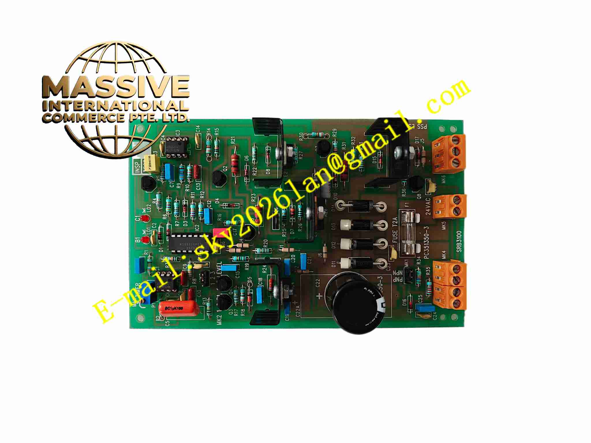
Description
DANFOSS SRB3100
Technical Specifications Brand: Danfoss Model: SRB3100 Power Supply: 24 VDC Safety Input: Dual-channel safety signal inputs Safety Output: Force-guided relay contacts Operating Temperature: -20°C to +60°C Humidity: 5% to 95% non-condensing Mounting: DIN rail mounting Protection Grade: IP20 for cabinet installation
Functional Features Dual-channel input monitoring detects short circuit and cross-wiring fault on safety circuits. Force-guided relay contacts ensure reliable safety contact action and prevent contact welding hazard. Integrated self-diagnostic function checks internal relay health status during operation. LED status indicators display power supply state, input signal status and fault alarm condition. Manual reset mode and automatic reset mode are selectable according to machine safety requirement. Multiple safety contact sets for controlling actuator power cut-off and fault notification.
Application Scenarios Packaging machine safety interlock, conveyor system emergency stop control, machine tool safety door monitoring, material handling robot safety protection, food processing machinery safety circuit.
Performance Parameters Fast safety contact response upon safety signal trigger. Continuous fault detection for safety wiring loop anomalies. Force-guided contacts maintain safety integrity even under contact wear condition. Stable operation under industrial electromagnetic interference environment. Long service life under repeated safety switching cycles.
Material Composition Housing: Flame-retardant reinforced plastic. PCB: FR4 printed circuit board coated with conformal coating. Core Components: Force-guided safety relays, input signal conditioning chips, diagnostic microcircuit, surge suppression components. Terminals: Tin-plated copper screw terminal blocks.
Structural Features Compact rectangular DIN rail enclosure. Front panel fitted with LED status indicators and terminal identification marking. Rear DIN rail clip enables fast installation and removal from standard DIN rail. Internal circuit layout separates low power signal circuit and high-current output contact circuit. Screw terminals arranged on front side for convenient field wiring operation.
Working Principle Safety field devices such as emergency stop switches feed dual-channel input signals to module terminals. Internal diagnostic circuit continuously compares two input channel signals and detects wiring faults. When safety input triggers, safety relay de-energizes and force-guided contacts open to cut off power supply to machine drive system. Internal self-test circuit verifies relay function in each operation cycle and activates fault indication if relay malfunction detected.
Installation Requirements Mount module vertically on standard 35mm DIN rail inside control cabinet. Route safety signal wiring with shielded twisted pair cable. Separate safety circuit wiring from high-power motor cables. Connect protective earth terminal to cabinet grounding system. Select reset mode according to machine risk assessment result before commissioning. Test emergency stop and safety door function after wiring completion.
Usage Notes Cut off 24VDC power before modifying safety wiring. Do not parallel external contacts onto safety relay output circuit. Inspect terminal screw tightness periodically in vibration-heavy environment. Replace module immediately when persistent internal fault alarm appears. Verify safety function after every wiring change or module replacement.